diy solar

diy solar

Advice on cable and fuse sizing for battery rack

Ron-ski

Solar Enthusiast
Joined
Jun 4, 2022
Messages
186
Location
Broadstairs, Kent, UK
I'm building my own 48v battery rack, capable of holding 4 batteries consisting of 16 EVE 280ah cells each. To start with I'll only have one battery, I will probably add another once funds allow. Electrician will be doing the AC side, and I'm dealing with the DC side.

Equipment list so far for the battery/inverter side of things:

  • Victron Quattro 48/10000 (will be grid tied)
  • 275A isolator switch for inverter
  • Lynx Power In (can be fused)
  • Lynx Smart Shunt 1000
  • Lynx Distributor
  • JK BMS 200A (B2A20S20P-CAN)
  • 250A two pole DC circuit breaker/switch
  • 160A two pole DC circuit breaker/switch
  • 16 Eve 280Ah cells
I already have the BMS, cells and both the above DC circuit breakers, I was going to build my own bus bar, but I think using the Lynx system will be cleaner.

Cable run from the battery to the Lynx Power in would be about 3.2m (bottom shelf), and I was looking at using 70mm cable, something like this.

I don't 100% trust the DC breakers so would also like a fuse close to the battery positive which I understand has to be a T class, but not sure on what the rating should be?

Also not sure if I've got the correct rated DC circuit breakers, 160A was intended for individual batteries, 250A to turn off/protect the whole rack (not needed with Lynx system)?

Should I also fuse the Lynx Power in? If so what fuses?

The inverter is rated at constant of 8000w, but a peak of 16000w, although I doubt we'll draw that much, so this confuses me somewhat as what the fuses should be used should there be a large peak.

Also how critical is it that all the battery cables are the same length?
Powerwall.jpg
 
Last edited:
Also how critical is it that all the battery cables are the same length?
Very critical. There’s an article with math in my signature block to show math. That adds up to a lot of cable and can also add a bit of cost to a build. There’s an option in there to have some different cables with four batteries.

That applies to the main battery cables that parallel the battery. If this is from the main negative or positive to system busbars, that is not so important.
 
@chrisski Yes I was coming to the conclusion that running 4 pairs of battery cables at 3.2m was going to add up to a lot, so I was thinking it may well be cheaper to have a short busbar on the side of the rack, which the four batteries connect to, then use one pair of 90mm cables to run up to the the lynx shunt doing away with Lynx Power in, or relocate it to the side of the rack, but my own busbar may be more compact.

If the individual battery cables are shorter, I could probably drop down to 50mm or 60mm cables for the battery to side mounted busbar.
 
I only have 2 X 8s eve 280 ah in parallel, and that I made with wires of equal length, method 3. Someone posted how much wire he saved when he assembled his cells with method and he said it was quite a bit.

A9993BF4-17F0-42E9-A373-C8B7C4329045.jpeg
I admit, I d not understand why this method 4 is a close runner up to method three. I do understand why method 1 and 2 (not pictured but in the link) don’t work well, and some people who‘ve posted batteries going bad, the batteries seem to be going bad in accordance with the math, furthest away batteries last longer and closer die quicker.
 
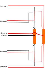
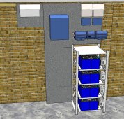
Method 3 is what I was thinking of in post number 4, it would use much less cable, and I could easily keep the cables to each battery exactly the same length. The main cables from the rack side mounted busbar could run up the brick pillar, directly to an upside down Lynx shunt and fused Lynx Power in, which shortens the main cables as well.
 
Last edited:
This is basically what I've come up with, all battery cables will be the same length. I'll use a short busbar, the top batteries will both connect using the same bolt, one cable either side of the busbar, presumably this is OK? The bottom two batteries will connect the same way to the bottom of the busbar, and the main power take off will be from the centre of the busbar.

Now I just need to clarify fusing, oh and find somewhere that can supply a short length of suitably tinned and sized busbar.

Battery Cabling.png
 
Blueseas has nice bus bars looks like you’d need 5-6 terminals.
 
Should I also fuse the Lynx Power in? If so what fuses?
I don't think the Power In needs fuses. Nice Drawing. Sketch Up?

I don't believe you need to install the shunt upside down. You can reverse a few tiny wires on the shunt allowing you to install the Power In on the right hand side of the Shunt. That's what I did.
 
@740GLE Thanks, yes they do have some nice busbars, but rather pricey - I'm going to email a few companies and see if anyone's got a couple off offcuts, only need 2 x 150mm of suitably size busbar, 8 x 30 minimum, as that's what's in the Lynx Power in etc.

@OzSolar Thanks, yes it's drawn in Sketchup. Useful to know regarding the shunt, but having the power in upside down actually makes running the MPPT cables more straight forward. It's also tempting to run the inverter cables directly off the end of the Power in, although it won't be fused but the shunt will be and the MPPT connections can be. Apparently there are a set of labels included for when they are mounted upside down.
 
Fuses.....I'm so confused, and the more I read the more confused I get.

Battery cable will be sized well over the highest fuse rating.

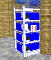
As per the picture above I'm building a rack that can hold four batteries, but I may just use two, they will each be 16 x EVE 280ah cells. Each battery will have a 200a JK BMS.

Inverter will be Quattro 48/10000 which can supply a constant 8000w.

I've found this calculation mentioned several times on here:

8000 / .85 / 48 = 196.07843 dc amps
196.07843 * 1.25 fuse factor = 245 fuse amps

But Victron recommends a 400amp fuse for the Quattro 48/10000


I'm having a master dual pole breaker for the entire rack, and then individual dual pole breakers for each of the four batteries. This allows me to easily isolate the whole rack, or individual batteries. They would also protect the T class fuses (they are expensive!!!) but I don't totally trust the breakers, so T class for belt & braces!

So should I go with a whole rack 400a T class fuse, and 350a breaker?

For the individual batteries 250a T class and 200a breaker?

I currently have already purchased a 160a and a 250a breaker, ideally I'd like to use these, but I'm now not sure they are rated correctly?
 
Fuses.....I'm so confused, and the more I read the more confused I get.
You are not alone.
I've found this calculation mentioned several times on here:

8000 / .85 / 48 = 196.07843 dc amps
196.07843 * 1.25 fuse factor = 245 fuse amps
That math computes the minimum size fuse.
The wire needs to be able to handle 245 amps minimum.

But Victron recommends a 400amp fuse for the Quattro 48/10000
I don't want to speculate on why Victron does what they do.
I'm guessing Victron has specificed a 400 amp fuse and 4/0 wire(or metric equivalent)
They are fusing for the wire as would I.
They probably want the wire nice and big so that the voltage droops less on a surge.
Because the fuse for the inverter branch circuit protects the wire and any passive wire like devices in the circuit.
It doesn't protect the inverter.
The feeder(battery circuit) protects the feeder circuit and the battery in the event that the BMS has already welded closed.
The feeder over-current protection should be as close as possible to the battery positive terminal.
If the dc core is not grounded then double pole disconnect is required.
 
Last edited:
Whats your thoughts on the fuse sizes for the individual batteries and all breakers ratings please?
If you are asking me I would need more information.
Are you planning for a pre-charge circuit?
What other loads and/or charge sources will be connected on the system side of the shunt?
Are you going to bond the dc system to the planet?
 
1. If you are asking me I would need more information.
2 .Are you planning for a pre-charge circuit?
3. What other loads and/or charge sources will be connected on the system side of the shunt?
4. Are you going to bond the dc system to the planet?

  1. Yes I am, thank you.
  2. I will most likely install one, but as its a grid tied inverter I understand it would precharge the capacitors if grid power was present, and switched on first prior to the batteries. However the system will be capable of working without the grid, so it would be prudent to install one as its relatively straight forward from what I've seen.
  3. Quattro 48/10000, 2 x SmartSolar MPPT 150/45, Victron Smart Shunt, Cerbo GX
  4. I don't know. Tried Googling today but comes up with all sorts of other stuff, so I've no idea of the pro's and con's of doing this, or whether its a requirement in the UK

I was considering using the Lynx Smart Shunt VE, but its three times the price of the normal shunt, and all I really gain is a smart looking case, even the fuse holder is redundant as I'm going to be installing a class T fuse.
When you say grid tied, do you mean you are going to export power to the grid?
 
I've attached my suggested topology.

Because each battery has a smart bms that includes current accounting, I've decided to omit the shunt and save you some money.
If you really want a shunt just stick a lynx shunt between the lynx power in and the lynx distributor.
Because each battery has a fet based bms that has administrative disconnect, I've used class-t fuses and omitted the breakers to save you money.
The administrative disconnect for each solar charge controller is a dpst switch between the panels and pv side of the solar charge controller.
The Quatrro gets a 300 amp fuse because that is the largest 48 volt mega fuse that Victron has.
If you can find a 400 amp mega fuse with the same or better voltage rating that would be good.
You could add a pre-charge resistor to the disconnect switch between the busbar and inverter.
The dc negative bus equi-potential bond is though the Quattro chassis lug to the ac ground.

I suggest to mount the lynx product stack vertically on the side of the battery rack.

The topology document is textual and not code.
It is in fact human readable.
The legend block describes all the elements that follow.
If you have questions I'll be glad to answer.
 

Attachments

  • Ron-ski.txt
    1.9 KB · Views: 26
Last edited:
When you say grid tied, do you mean you are going to export power to the grid?

Thank you for the replies.

Yes, and if the inverter can't supply enough power, then power is imported from the grid. In summer there would be an excess, in winter months the idea is to charge the batteries with off peak electric, which is about a third of the price..

I'm rather short on time this morning as I have to get to work, but a few questions to help me understand.

Thank you for the topology, out of curiosity is there some sort of program that can visualise it ?

Is there really any need to use a Lynx distributor? I've got 50 amp dual pole MCBs to sit between the MPPT's and Lynx Power In.
Between each MPPT and solar combiner is a 32 amp dual pole MCB.

Why use a 300a Mega, why not install a 400a T Class?

I will use a Victron shunt, simply as it ties in better with their software.
 
Thank you for the topology, out of curiosity is there some sort of program that can visualise it ?
Not until you write one.
Is there really any need to use a Lynx distributor?
No but the I'm big fan of the feeder/branch design pattern.
A fused busbar makes that really elegant.
Also the fused busbar approach means less joinery which means less resistance which means a more efficient system.
My philosophy is best described by Antoine de Saint-Exupéry as "A designer knows he has achieved perfection not when there is nothing left to add, but when there is nothing left to take away."
I've got 50 amp dual pole MCBs to sit between the MPPT's and Lynx Power In.
The power_ins are are what the batteries terminate on .
The distributor is what the loads and charge sources terminate on.
If you don't want to use a power in that is fine then you will need to fuse each each load or charge source.
45 service amps / .8 fuse headroom = 56.25 fault amps.
By the standard calculation your 50 amp MCBs are to small to go between the MPPTs and the positive busbar.
Between each MPPT and solar combiner is a 32 amp dual pole MCB.
Nice.
Why use a 300a Mega, why not install a 400a T Class?
Because only mega fuses fit in the lynx distributor.
If you don't want to do structured wiring that is fine.
I will use a Victron shunt, simply as it ties in better with their software.
That will be the choke point unless you use the lynx system.
 
Last edited:
Back
Top