True, I'm thinking if I top balance I will then be able to run a capacity test without bottom balancing. I'm on the road so we see how that works when I get home to my adjustable CC DC chargerIt doesn't make sense to top balance and bottom balance.
If you are using a balancing BMS then you almost certainly want to top balance.
You are using an out of date browser. It may not display this or other websites correctly.
You should upgrade or use an alternative browser.
You should upgrade or use an alternative browser.
Big Battery 24v A123
- Thread starter MrNatural22
- Start date
John Frum
Tell me your problems
- Joined
- Nov 30, 2019
- Messages
- 15,233
A battery can only be balanced to one reference point.True, I'm thinking if I top balance I will then be able to run a capacity test without bottom balancing.
Why are you considering bottom balance at all?
Maybe you know something I don't.
Sorry I shouldn’t be using that term, I’m a noob. I just want to see it hit 20v and remain in balance. At this point that is not happening.A battery can only be balanced to one reference point.
Why are you considering bottom balance at all?
Maybe you know something
John Frum
Tell me your problems
- Joined
- Nov 30, 2019
- Messages
- 15,233
For our application we top balance our cells so they are synchronized at ~3.65 volts.Sorry I shouldn’t be using that term, I’m a noob. I just want to see it hit 20v and remain in balance. At this point that is not happening.
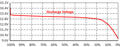
Since the cells we use are not perfectly matched the further you discharge them from the syncronization point the more they diverge.
That is normal and to be expected.
For a test you can discharge them until the first cell hits 2.5 volts(check the cell doco).
That will be the weakest cell.
The others will be at various voltages above 2.5 volts.
Now as you recharge back to the synchronization point they cells should re-converge.
This won't be perfect either and that is where the balancing bms comes in.
Hopefully it can tweak the balance during normal cycling.
Depends on the actual cells you have how much intervention is required to keep them acceptably balanced.
Under normal operating conditions the cells tend to diverge less if you don't draw them to far down into the low knee.
Last edited:
Thanks for the insight. So you would stop the capacity test when only one cell hits 2.5v ? I’m curious what mV delta you would deem acceptable for good cells at that pointFor our application we top balance our cells so they are synchronized at ~3.65 volts.
Since the cells we use are not perfectly matched the further you discharge them from the syncronization point the more they diverge.
That is normal and to be expected.
For a test you can discharge them until the first cell hits 2.5 volts(check the cell doco).
That will be the weakest cell.
The others will be at various voltages above them.
Now as you recharge back to the syncroniztion point they cells should re-converge.
This won't be perfect either and that is where the balancing bms comes it.
Hopefully it can tweak the balance during normal cycling.
Depends on the actual cells you have how much intervention is required to keep them acceptably balanced.
Under normal operating conditions the cells tend to diverge less if you don't draw them to far down into the low knee.
John Frum
Tell me your problems
- Joined
- Nov 30, 2019
- Messages
- 15,233
Yes most of the lfp cells we use specify 2.5 volts at the lowest safe voltage.Thanks for the insight. So you would stop the capacity test when only one cell hits 2.5v ? I’m curious what mV delta you would deem acceptable for good cells at that point
Some older cells allow discharge to 2.0 volts.
That is why I suggest you check the cell doco.
Most of them describe their exact method to capacity test.
In normal operation I would set the bms to trip when the first reached ~3.0 volts.
As for vm delta everyone has their own opinion.
I would say less than <100mv is acceptable.
More important than the actual delta is how well the cells re-converge on a full charge.
In other words its the drift in the delta over charge/discharge cycles that is more important than the actual delta.
Put another way, its whether your bms can keep the cells in line.
Personally I would disable bms balancing for the first dozen or so cycles to see how well the cells hang together without intervention.
Appreciate the time, the cells on my A123 recover very quickly to 5-10mV delta. Although near the bottom and top I’ve seen them hit a 300mV delta. At that point I’ll cut off any load or charge and let the BMS balanceYes most of the lfp cells we use specify 2.5 volts at the lowest safe voltage.
Some older cells allow discharge to 2.0 volts.
That is why I suggest you check the cell doco.
Most of them describe their exact method to capacity test.
In normal operation I would set the bms to trip when the first reached ~3.0 volts.
As for vm delta everyone has their own opinion.
I would say less than <100mv is acceptable.
More important than the actual delta is how well the cells re-converge on a full charge.
In other words its the drift in the delta over charge/discharge cycles that is more important than the actual delta.
Put another way, its whether your bms can keep the cells in line.
Personally I would disable bms balancing for the first dozen or so cycles to see how well the cells hang together without intervention.
John Frum
Tell me your problems
- Joined
- Nov 30, 2019
- Messages
- 15,233
As I said before its normal for the cells to diverge at the bottom.Appreciate the time, the cells on my A123 recover very quickly to 5-10mV delta. Although near the bottom and top I’ve seen them hit a 300mV delta. At that point I’ll cut off any load or charge and let the BMS balance
How low is your daily driver low cell cutoff?
If they keep converging on <10mv at the top then you have a very good top balance.
John Frum
Tell me your problems
- Joined
- Nov 30, 2019
- Messages
- 15,233
If you have a smart bms you might set it to balance only during charge and only above both float and full resting voltage.
Since your balance is actually quite good I would try turning it off and see how well the cells hang together without intervention.
You can always re-enable balancing if they drift.
Since your balance is actually quite good I would try turning it off and see how well the cells hang together without intervention.
You can always re-enable balancing if they drift.
As I said before its normal for the cells to diverge at the bottom.
How low is your daily driver low cell cutoff?
If they keep converging on <10mv at the top then you have a very good top balance.
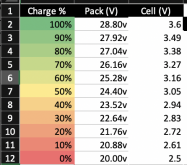
For daily use I will probably hang between 3-3.4v per cell. I made this chart to give me an idea where I am percentage wise. Granted its not totally accurate, but it gives me a general idea where I'm at.

John Frum
Tell me your problems
- Joined
- Nov 30, 2019
- Messages
- 15,233
Where did you get those numbers?For daily use I will probably hang between 3-3.4v per cell. I made this chart to give me an idea where I am percentage wise. Granted its not totally accurate, but it gives me a general idea where I'm at.
View attachment 26444
I doubt that there anything close to 10% capacity between 2.61 and 2.5 volts.
Like I said it only provides a general idea, I made it myself. Its =((MAX-MIN)*%)+MIN , let me know if you have a better formulaWhere did you get those numbers?
I doubt that there anything close to 10% capacity between 2.61 and 2.5 volts.
John Frum
Tell me your problems
- Joined
- Nov 30, 2019
- Messages
- 15,233

How to Find Happiness With LiFePO4 (Lithium-Ion) Batteries –...
By: Rob Beckers You have just sold your first-born into slavery, remortgaged the house, and bought yourself a lithium-ion battery! Now you want to know how to take care of your precious new purchase: How to best charge lithium-iron batteries, how to discharge them, and how to get the maximum...
Benaranguren
New Member
- Joined
- Feb 14, 2020
- Messages
- 17
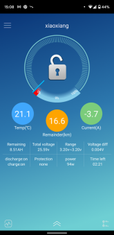
@ExternalG It's been a few days now and this is currently what the spread looks like towards the bottom end. This is about 24.467V pack voltage with a min-max delta of 84mV DC.Ok, After contacting bigbattery, they sent me 2 replacements. The first replacement had the same issue where cell 2 was dipping faster than the rest of the pack. The 2nd replacement had the same issue as my first battery where cell 7 was dipping.
I refuse to give up on this battery so I did more reading. As previously posted by other users, these battery chemistry has a steep slope once you go below ~3V and there's a flat region when cells are at nominal voltage. Same steep slope at the other end when charging. My initial thought is to bottom balance. My theory is when the battery has a decent charge (3.2V) then they are all in the flat region. But where in the flat region you are, you don't know. In my case cell 7 had a 3.23V reading but it was still closer to the roll off than the rest of the pack. And since I'm not charging this 100%, cell 7 doesn't move away from this hill.
Bottom balancing may have worked because I would force all cells to all be in the same spot where it's close to the hill. So when I charge the entire pack, they all move away from this knee, and when the battery is discharging, they all reach the knee around the same time.
But this would mean I would have to discharge 7 cells. So, I went a different way. I bought a power supply and connected it to cell 7 and charged just this cell by itself so I know it's farther away from the knee than it used to be.
Tonight is the first time I'm discharging it so we'll see what happens tomorrow and where they all stand.
This is how the battery was when I first got it.
View attachment 25494
This is after giving cell 7 a boost. I've never seen all cells this close ever before.
View attachment 25495

Benaranguren
New Member
- Joined
- Feb 14, 2020
- Messages
- 17
I don't intend to reach the 20-28.8v limits and I'm ok with the current performance I'm getting. I'm operating between 24V-26V daily. All the cells converge when charged with only a delta of 4mV. I thinking boosting cell 7 in my case definitely helped.@Benaranguren any update on reaching 20v-28.8v? I’m having the same issue and I’m considering opening it up to bottom balance and top balance the cells individually

whatismouse
New Member
- Joined
- Oct 11, 2020
- Messages
- 76
From the big battery website:
"Single cell over-discharge protection voltage:
Can anyone explain how it can be a range rather than a fixed voltage? And for some reason I had the figure of 2.5V in my head for a single cell LVC.
I drew my two A123's in series down to 46V today, the first semi-complete discharge I've done. My weakest cell between the two packs was 2.77V immediately when inverter hit LVC @ 46V. This battery was 24.15V, the other was 24.90V. That's not much wiggle room before the BMS trips (hence why I was trying to figure out exactly when it would). So I adjusted my inverter LVC to 48V to be safe for now. Perhaps if cell voltage deltas tighten after a few cycles I can drop the Inverter LVC to eek out some more capacity?
"Single cell over-discharge protection voltage:
- Min: 2.15V
- Standard: 2.7V
- Max: 2.8V"
Can anyone explain how it can be a range rather than a fixed voltage? And for some reason I had the figure of 2.5V in my head for a single cell LVC.
I drew my two A123's in series down to 46V today, the first semi-complete discharge I've done. My weakest cell between the two packs was 2.77V immediately when inverter hit LVC @ 46V. This battery was 24.15V, the other was 24.90V. That's not much wiggle room before the BMS trips (hence why I was trying to figure out exactly when it would). So I adjusted my inverter LVC to 48V to be safe for now. Perhaps if cell voltage deltas tighten after a few cycles I can drop the Inverter LVC to eek out some more capacity?
whatismouse
New Member
- Joined
- Oct 11, 2020
- Messages
- 76
I'm operating between 24V-26V daily.
Just curious why you only charge to 26V?
Benaranguren
New Member
- Joined
- Feb 14, 2020
- Messages
- 17
26v is 90% of the max voltage 28.8V (3.6V per cell * 8). Also, my Renogy SCC seems to stop charging at around 26.4VJust curious why you only charge to 26V?
Benaranguren
New Member
- Joined
- Feb 14, 2020
- Messages
- 17
Ok. I think I now understand what's going on and what's preventing my SCC from charging higher than 26.4VDC.26v is 90% of the max voltage 28.8V (3.6V per cell * 8). Also, my Renogy SCC seems to stop charging at around 26.4VI'm getting an Outback flexmax 60 soon so we'll see if that helps.
I just don't have enough solar power generated
To simply put, if I have 300W coming from my meager 4x100W panels in series, this translates to about 68VDC @ 4.4A going into the SCC. The MPPT controller then tries to optimize this for my 24V battery bank. Ideally, the battery bank would get 300W / 28VDC = 10.7A.
If the size of my battery is 70AH then it would take 6.542 hours to top off or reach floating stage of 27.4VDC.
However, I also use the 4 panels to power some circuits and 300W is only during solar peak.
So my obvious next step to me is to add more panels.
etatdiysolar
New Member
- Joined
- Jun 29, 2021
- Messages
- 26
Can you use these in the same bank with standard LiFePO4 batteries? I have a couple 48V packs, I want to use along with some standard 48V packs. Best I can tell the max charge voltage is slightly less and the internal resistance is about 1/2 of the normal packs. When I connect them together everything works fine but the lower IR causes the A123 batteries to discharge with a higher current than the others but it levels out as SOC gets lower.. and when charging they pull a lot more current than the other standard packs but it also levels out as they charge ahead of the others... each pack has it's own BMS.. no idea if long term problems could arise..??
Similar threads
- Replies
- 1
- Views
- 140
- Replies
- 3
- Views
- 262
- Replies
- 55
- Views
- 4K
- Replies
- 111
- Views
- 7K
- Replies
- 8
- Views
- 842


