diy solar

diy solar

Budget gone wrong setup

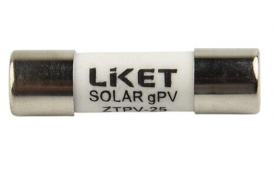
It comes with 15A fuse installed in it!
Ok you're good to connect a 250W panel (22V 6.87A from series connection) to each of those MC4 inputs.
2x 250W per combiner box. Output to an SCC.

The green breaker is your solar cutoff switch.

and I might have possibly damaged it due to the above
No its probably just fine. Does it look fine (no swelling and holds a voltage same as the others?).
 
Ok you're good to connect a 250W panel (22V 6.87A from series connection) to each of those MC4 inputs.
2x 250W per combiner box. Output to an SCC.
Given this solar panel specs

2022-12-10_08-26-51-png.123914

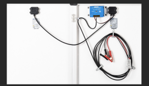
Factory Panel setup (2 * 125W 22V VoC pre-wired in parallel)
250W 22V VoC / 18.2V Vmp / 13.74A Imp == 2 * 125W 22V VoC / 18.2V Vmp / 6.87A Imp
==series wire modification==>
250W 45V VoC / 36.4V Vmp / 6.87A

So I'd desolder the pre-wired parallel connection and connect 2 * 125W in series and that should be connected to the PV box via MC4!
just a tickling question, is 15A fuse too big for 6.87A input?


No its probably just fine. Does it look fine (no swelling and holds a voltage same as the others?).
I've wired 3000W inverter to the battery and it drains very quickly and can't hold voltage :(
used about 200W for 3hours and voltage dropped to 10.8V from 13.6V (voltage reading from the damaged PWM charge controller)
I should have read the voltage from the battery directly but at that time I couldn't find the reader from a pile of moving boxes...
 
So I'd desolder the pre-wired parallel connection and connect 2 * 125W in series
Just remove the blue SCC which has a + from one 125W panel and the - from the other 125W panel. Connect these 2 wires and you have your series connection.
just a tickling question, is 15A fuse too big for 6.87A input?
Yea, you don't really need a fuse for just 2 strings. You're essentially using your combiner box to combine, lightning protection and cutoff switch.
 
I've wired 3000W inverter to the battery and it drains very quickly and can't hold voltage :(
used about 200W for 3hours and voltage dropped to 10.8V from 13.6V (voltage reading from the damaged PWM charge controller)
It may have limited capacity then. But since you're connecting in parallel with the other one, it may provide some capacity. If you notice any heat, swelling or funny business i'd stop using it.

I'm not sure i'd trust the readings from a damaged PWM controller. It was accepting input from the MPPT charger on the panels? Who knows how the 2 chargers were interacting. Label it and keep an eye on it thru a few charge cycles and you trust it.
 
Just remove the blue SCC which has a + from one 125W panel and the - from the other 125W panel. Connect these 2 wires and you have your series connection.

Yea, you don't really need a fuse for just 2 strings. You're essentially using your combiner box to combine, lightning protection and cutoff switch.

2022-12-10_10-58-18.png
2022-12-10_11-11-29.png
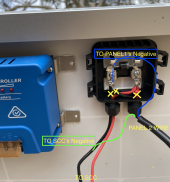
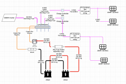
I've done my best drawing it!
But then... with out fuse the PV Box wouldn't work!
36.4V Vmp / 6.87A
Based on this, I should get 8A/10A fuse per each string!
2022-12-10_11-15-12.png
 
I'm not sure i'd trust the readings from a damaged PWM controller. It was accepting input from the MPPT charger on the panels? Who knows how the 2 chargers were interacting. Label it and keep an eye on it thru a few charge cycles and you trust it.
I've disconnected the MPPT controller and wired the panels into PWM controller thinking the controller will figure out the battery type automatically... but the PWM controller was set to 24V Lead Acid charge profile. I left it for about 1 full day then realised I set it wrong and changed the profile to Lithium.
Also forgot to mention that I've drained the brand-new battery (50% charged from purchase) to 10.8V (where the Inverter cuts the discharging).
From this point, I never knew if the PWM controller was actually charging the battery. I've currently disconnected the battery for fear of losing $800!
 
I've done my best drawing it!
But then... with out fuse the PV Box wouldn't work!
36.4V Vmp / 6.87A
Based on this, I should get 8A/10A fuse per each string!
2022-12-10_11-15-12.png

Where did the 36.4Vmp come from? This is a new number.
All the previous work was based on this 250W panel being 22.9V. I'm lost again.

You don't need to fuse 2 strings in parallel, save your money.
 
Where did the 36.4Vmp come from? This is a new number.
All the previous work was based on this 250W panel being 22.9V. I'm lost again.
this will help me describe my system now that I learn so much from you guys.

22.9V was the voltage read from the open-circuit wire (VoC)
36.4V was calculated 18.2(250W panel spec) times 2 (since I'm going to modify 2*125 from parallel to series) for Voltage Maximum Power (Vmp)

250W = 18.2V(Vmp) * 13.74A(Imp), voila! I naively assumed that was how it's measured.
But it seems it's more important to look at Open Circuit Voltage (Voc) and Short Circuit Current (Isc) when designing.

2022-12-10_22-18-35.png
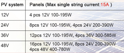
My confusion comes from the table the solar panel seller listed.
I wasn't quite sure which category my panels belong to.
Perhaps the panel voltage should be based on Open Circuit Voltage (VoC) which is 22.9V (45.8V in series)


You don't need to fuse 2 strings in parallel, save your money.
awesome! I'll leave the 15A fuse in that came with the box and save the money for buying other fuses.
 
Last edited:
Update:

2023-04-05_13-58-36.png

I had to purchase a new Inverter/Charger as the 3000W inverter from Adventure Kings failed quickly.
Also, I connected the panels in 2S (250W * 2, 45.8 VoC) and mounted to each of the PV Box.
PV Box here is unnecessary as I'm only using one pair of sockets out of 4 but serves the purpose of fuse and circuit breaker.

I expected it to produce 40A each from one PV BOX.
However, it's only producing 20A at max for each 40A MPPT SCC. (around 250W each)
So I thought it was because I had my panels connected in series, not parallel.
But then I find this ARTICLE that it shouldn't matter as that's what Solar Charge Controller should handle.

It'd be great if anyone can spot what I'm missing here.
** Getting an Inverter/Charger turned out to be the best decision I made. I can charge the battery bank through the Inverter/Charger from a generator!
 
What model is your new charger?
Have you measured volts and amps from your array?

However, it's only producing 20A at max for each 40A MPPT SCC.
why do you say for each 440A MPPT SCC? Do you have more than one?

If you have a 500W array, the MPPT should do
500W / 14V charging = 35.7A at 100% efficiency

But if your batteries are full it will pull less current, only what is needed for charge profile.
 
What model is your new charger?
Have you measured volts and amps from your array?


why do you say for each 440A MPPT SCC? Do you have more than one?

If you have a 500W array, the MPPT should do
500W / 14V charging = 35.7A at 100% efficiency

But if your batteries are full it will pull less current, only what is needed for charge profile.

2023-04-05_16-45-09.png

2023-04-05_16-48-39.png

Sorry for the confusion.
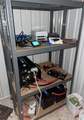
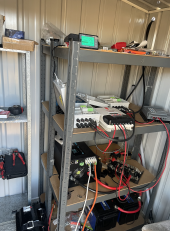
I attached the latest photo of the setup.
I've got
2 * 40A MPPT SCC (different brands. 1 from KickAss / 1 from Altronics)
4 * 250W Solar panels (each 22.9VoC)
Each MPPT SCC is charging 20A maximum under full sun. (regardless battery state)
And each solar PV measures around 45V
 
And each solar PV measures around 45V
That sounds right. What is the current? Do you have a digital meter to test the current in full sun?

I attached the latest photo of the setup.
Ok, i understand now. Thats a lot of extra equipment in there! A combiner box for each string not a bad thing as a breaker to cutoff solar is mighty handy.

If you do tests, make sure that only one string is active as its voltage, if charging, will affect the behavior of the other. Not saying they will slam dance but they will affect each other (not a bad thing but the settings should be nearly identical if you want them both to work the same).
 
That sounds right. What is the current? Do you have a digital meter to test the current in full sun?


Ok, i understand now. Thats a lot of extra equipment in there! A combiner box for each string not a bad thing as a breaker to cutoff solar is mighty handy.

If you do tests, make sure that only one string is active as its voltage, if charging, will affect the behavior of the other. Not saying they will slam dance but they will affect each other (not a bad thing but the settings should be nearly identical if you want them both to work the same).

Just ordered a clamp meter!
One thing I notice is that the KickAss SCC measures different Voltage from the other SCC.

E.g.,
Battery monitor reads 13.4V
KickAss SCC reads 13.5~13.8 fluctuating
Altronics SCC reads 13.4V (same as the battery monitor)
 
It's annoying on the supacenter website that they are selling Lifepo4 batteries alongside incompatible charge controllers.
Lots of things I purchased from 4WD supacentre broke :(
- 3000W inverter
- fan failure
- too much power drawn
- Outdoor water heater
- died after 4 months
And the panels seem to be undercharging but still investigating...
 
Back
Top