diy solar

diy solar

Building the sickest ® VAWT ever. Brilliant minds unite please!!

I am not sure if I ran this experiment correct or not.

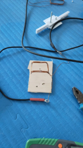
I am trying to establish if a serpentine coil is just as capable as a closed looped coil in generating a field when magnets run over them.

But the test was the same closed loop coil but then the second run with the ends bend away as it is not doing much for the generation of electricity when magnets pass over there was my reasoning.

Anyway there is no difference that I could find between a non bend coil and the one on the photo below
1709890731394.png

the field stays the same whether I bend away the legs or not
 
I am soo sorry that I am still not there.

If I want to keep at an inner radius of 300mm then 1mm diam wires will just not make it (and I kind of knew already :( )

So even though a well respected, and one that I trust and love, knows his stuff on fieldlines told me to always stay at and between 0.8mm diam and 1.3mm. (Now here comes the problem)
I only have 0.71mm diam wire in bulk. And this early in the process in where I still have not asked (out of shame and general reluctance because I can feel a crowd a bit) why these specific advised on dimensions of wires!

Anyways here goes with the 0.71mm wire test at 100 windings.

(the context is still a 300mm inner radius)

1709919580900.png

haah yes I know what you are thinking. "But brandubly my dear conjurer of weird things. Why are you still on a 600mm inner radius then?"

Well that is a short cut.
Please forgive me that I really am not looking forward to hard work all the time. So sometimes shortcuts seem a viable option :)
The magnets are spaced and oriented as if they would be on an 300mm inner radius.
And since all I care about is frequency then, with my limited understanding , things are comparable.

and now I realize I was going a bit too fast but I just figured. heyy, why will we not let the 3 phase to dc rectification process take care of the little lower than aimed for voltage? :)

1709920116666.png

Now please note that with thise full coils I am testing now we can actually simply extrapolate linearly. by 48 times.


Next up when my new variac is here is to see what kind of field I can get out of this coil when exposed to 52vDC
 
ahh by the way. I have read already a few chapters by now of this paperback that has gotten in in the meantime.

I still am not sure I can find what it is I am looking for to be honest though.

In generic terms it is a great book. Just like the first one I bought as a kindle.

But I still am unable to find where it leads me to learn on how to pull off what it is I am trying to pull off.

Can the owners of said book please recommend me a specific paragraph of a chapter? because I am renowned in missing important details when text becomes long :(
 
@justgary and everyone reading in,

It is going to happen this within 2 months projection after all.

I have already done so much of that PMA test bench analysis that I have a gut feeling that I can pull it off by now.

But to make sure I can adjust the velocity of the PMA in case things go south I am letting go of the direct drive for now.

I am printing pullies as we speak for a 1 to 1 ratio timing belt driven PMA so it can be detached from the turbine.

If things suck hard I can always change the ratio and see if that improves things.

But if a 1 to 1 ratio works in practice then the direct drive will be back at a later time.

Think of the amount of time this will save to just dive in head first!!! let us deal with issues when we get there, if at all.

So this all is a friendly reminder that even though I am slow in nature. I do not forget everything I have ever read and sometimes. or rather often times your suggestions might just come back at a later time as the detaching of the PMA was also not my idea. Someone else suggested that.
 
I am starting to distrust this AI less and less.

You see it is also a matter of what information do we feed it and how do we counter/steer it into the right direction.

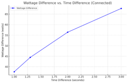
I for one now thoroughly believe that we have found a way to convert a measure meant of time to a power measurement.

1710016747439.png
Mind you and I didnot create this graph. I just went overboard and kept hammering this damned Ai to finally get my point. I went a little over budget sure but that does not matter in the pursuit of science.

Now this looks linear enough to me.
 
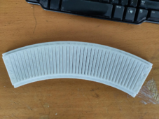
printing a T5 timing belt pulley with a 1mm nozzle was a bad idea :) but I kind of expected that but just wanted to see how precise I could get the teeth get it by tweaking the print settings.

But then I got impatient and switched to a 0.2mm nozzle.

The difference is night and day.

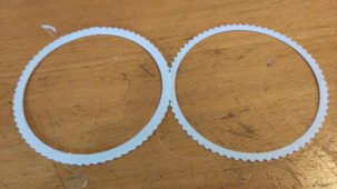
1710053943772.png
these are test prints for the t5 16mm pulley that will be installed on the turbine column
 
Next up when my new variac is here is to see what kind of field I can get out of this coil when exposed to 52vDC
got it, and send it back. what a load of crap that thing was..

clearly not QCed straight out of our friends from the east.

Now I am no advocate of speech that promotes a certain thinking of a certain country. But come on gang. We all know it. If you buy cheap you get junk. Especially from those parts of the world.

I should have resisted this deal that looked too good to be true.
 
And mind you that I blame our party playboy.

You know this guy that started out as a quirky book store owner of sorts.

Then by a stroke of genius or luck or both got him self a divorce, a large settlement, a hot chick and still a sweet amount of cash.

Jeffery my man, teach us how to do it!

Truth be told though I do not like amazon. Not al all!!!
 
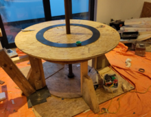
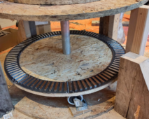
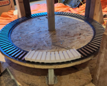
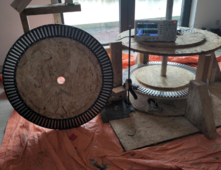
even when scaling down from a 600mm inner radius to a 300mm inner radius the alternator still looks scary!
1710177948201.png

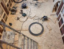
And look how much of the test bench we can chip away !

1710178001223.png

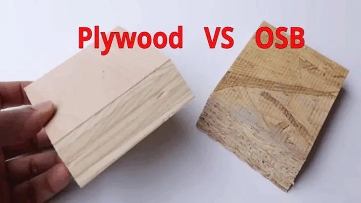
Now I still to this very day do not know why hedges dislikes OSB that much :)
 

Presumably, in the case of either, what our home improvement store carries will be the cheapest cr*p available.
 

Presumably, in the case of either, what our home improvement store carries will be the cheapest cr*p available.
nah brother. OSB type 3 is what I use. It is of constructional grade and can be exposed to limited water.

Mind you the key word here limited. This is just a proof of concept PMA. I will not let it go into service like this :)

type 3 is certainly not cheap and if we wanted to skimp on OSB then we can always go for the lesser grade of OSB one can find in the home improvement stores.

fun fact: the whole of the steel frame outside and inside of my home build are plated with this type of OSB. To provide the shearing resistance a frame needs. And I am talking about a large frame under wind load and potentially earthquakes of the lesser kind. Not a frame one puts up to segment internally.
and the floor frames were covered with the same type of OSB but then 22mm thickness rather that 18mm like on the vertical parts

During constructing we had a recurring puddle of water in the same spot on the flooring OSB for like 3 months. All that happened is that a few layers of the strands came loose and I removed them loose strands. Nothing nearly worrisome.
 
Last edited:
yessss!! finally i managed to to use a 1mm nozzle and still be able to create slits for the push through template without too much post processing!!!!.

you see the idea is to have the earlier template to pre form the stacked serpentine coil. And then move all 3 phases to the press through template.

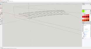
Now what is a stacked serpentine coil one might ask yes?

1710343406505.png

it is a single loop of 50 winds enough to twist the coils on them self's for 11 times as depicted here in the screen shot.
This would result in 12 coils with the start and end coil being half density. But these segments could still be overlapped and thus ending up with this continues loop I have been less than silent about in earlier times.

But that is only when one wants to go full force and I honestly do not want that. I want to go for 11 coils stacked serpentine so that the segmentabilitty comes back again. It all depends on how much voltage can I get out of 50 wires of 0.71mm and then twist them around enough so only the start and end coil are half coils. the rest are full coils of 100 wires.

And even if we hit the 52 vAC mark at 3.7Hz open circuit then the fat lady is not done singing yet.

No!!!! Now we need to establish if these shared between coil legs indeed only half the electromagnetic field they produce or somehow perform worse than their closed loop counter parts in relative terms.

You see I am of the firm believe that if a coil can't act as an electro magnet strong enough than voltage means nothing if one cares about wattage the coils in the PMA can deliver without overheating and melting down. I still think it is the electromagnetically resistance the coils can provide and then be overcome by the turbine whilst not melting down what essentially rates a PMA.

It is a complex subject that I trust is well defined in the books but books are not for people like me. I am more of a hands on guy!

1710344540332.png
 
since also on this software the search is simply just not as how a self respecting user of said search function would like it to operate I could not find my croc dundie telling kids what a real knife looks like.


Anyway that post was in the context of what real coils look like rather than the same old closed loop rehashed stuff we see over and over again in the books that we buy but do not get us anywhere.

Now croc dundee did call me a while back telling me about his thought on the matter whilst on his walkabout through the backlands.

And then it struck us both while on that talk.

That a stacked serpentine coil is in all intents and purposes similar to stacked closed loop coils yet then more efficient with wire usage.

Then I thanked Nick Dundee for the always inspirational talks we have!!
 
So I took a slight shortcut to see the field forming abilities of closed loop coil versus stacked serpentine coils.

And to my happy surprise sharing legs between coils (whether stacked serpentine or closed loop stacked) does NOT half the field in each coil.

So not only does serpentine (wheter single loop or stacked) reduce the total length of wire but also doubles the available field exposed to all magnets as opposed to traditionally spaced closed loop coils.

I hope I did it correctly but it would be such a shame if my findings turn out to be not well reached.

1710409896911.png

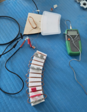
So I took a large 3 winds loop of wire and twisted it 10 times to end up with 11 stacked serpentine coils. Leg slot 1and 12 have only 3 wires. the ones in between 6.

Then I ran 1 amp through it and measured the field on several places.

To my surprise again the field in coil 1 and 11 are similar to that of the coils in between even though having only 75% of the total leg wires.

Then I ran the same experiment with a 6 winds closed loop coil of similar shape and ran the test in parallel.
The field was much higher in the closed loop coil.

Then I ran the experiment again with only the closed loop coil and then the field became similar to that of the stacked serpentine coils.

For sanity I then twisted the closed loop coil once ending up with 2 coils like in a stacked serpentine and the field did indeed not half. both coils have the same field but only opposite polarity.

I will still do the gravity torque tests but things are really looking good at the moment. I really hope I did not miss something critical and am heading towards a mayor blunder again.
 
I'm presently taking and analyzing magnetic fields at work.

3-axis Barrington sensor sampled by NI DAQ.

Multiple sources of 60 Hz fields, in a room with 3-phase and various complex loads.
That gives 120 degree phase increments for voltage, but current can lead or lag. And rectifier/capacitor circuits are non-linear, clipping in a way that generates harmonics.

Each of 3 axis gives a time domain sequence of measurements.
FFT reports amplitude of frequency components, also phase.
At first I thought of just computing amplitude as RSS of the three axis. But each has different phase.
That is, it isn't linearly polarized, it is elliptically polarized. Field rises to a peak in X, but as that component falls it rises to a peak in Y and in Z.

I'm trying to tabulate contribution of each source (coil) and adjust them to cancel each other.

There are magnetic field cancellation systems which simply attempt to zero sensor feedback with something like PID (whether implemented analog or digital.) But before making that do its work of actively driving opposite field, I'm trying to attack problem at the source.

Just the opposite of your goal. You want strong field, I want no field.
 
WOW!!!

There might be hope still yet for the single rotor (magnets) dual stator (coils.)

please bear witness to the following.

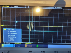
1710948948160.png

with a 2 coil serpentine twisted (stacked as we used to call it), while it is not even optimized yet! I get this.

1710949107742.png

let us call this 550 mvAC at the intend Hz of 3.7.
Now double that because of there is an extra one of this on the other side;

1710949225716.png

I officially am able to keep true to my projection I made earlier about the the 2 months blah blah blah.

Screw that. I want to do more research first!!!!!! :)

I realize that then we loose the steel enhancement. Yet that is nothing we can deal with by optimizing the coils. After all we have already 2 coils cramped into 8mm thickness and rather odd looking. Not at all optimum from the magnets.

I think this 40% increase given by the steel backing, that will be lost when going dual stator, can be overcome by using 50% more wires per coil.
 
Last edited:
OK gang! I now have some new data to use as guideline.

Adding the extra disk of 96 magnets at a 17mm spacing does nothing to enhance the field {1}edit, not field, i meant voltage producing capabilities{/1} when the coil is so thin like the test coils we are using now.
Now I know it will enhance but then we need fatter coils. But this is early testing still.

But here comes the kicker!!

Having a single 100 winds coil compete against a double twisted serpentine coil of 50 winds yields the same results in terms of voltage producing.

And that was to be expected as thy both have the same amount of wire exposed to the field perpendicular to the field.

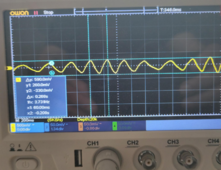
1710955022069.png

look how almost synchronous the waves are between ch1 the serpentine twisted into 2 coils and ch2 the single 100 winds coil.

This tells me that that serpentine, in one shape or another, is worth exploring as I can fit about 1 more coil using serpentine that way that using single coils.

Someone please challenge me on this as I need to get my head straight.
 
and I forgot to mention that the twisted serpentine exposes double or 200% more electromagnetic field to the magnets.

Here is my unconfirmed logic.

a single closed loop can produce x mT. when we twist that same coil into a serpentine then we get 2 x x mT.
Still the same amount of wire and resistance in that wire.
Now add to that the fact that twisted serpentine usees less wire than stacked coils would. Thus less resistance.

Somewhere in my logic there must be a mistake. otherwise why is not this a standard yet?

I can think of one thing though.

In a DIY setting one wants ease of production. Not something like I do with endless trail and error getting to a configuration that might perform a little better than the standard.
 
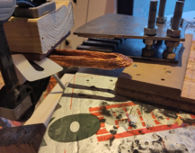
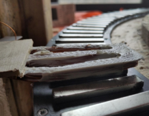
and this close up photo of the 2 coil serpentine was held into place with poly resin. I will order more as I am running out now :(

But I will also try (please Gary forgive me for still trying :( ) adding iron powder to the mix but this time not massage the coil wires into place.

Just to see if persuading the magnetic field through the wires by enhancing the magnetic permeability of the path (which is directly through the coils) will do anything for the voltage producing abilities of a coil

I know that one thing it will do is enhance the heat dissipation ability.

Another thing it is most likely to do is begging for shorted coils if not cast correctly.

But it might, just might also do something unexpected........

if cast correctly
 
and the windy season is closing to an end :( You know what! screw this again. I am going to hook things up just before there is no more wind to be had this season.

Motor to spin it should be fine for tests, especially unloaded.
Somebody here wrote than when investors come to see a wind farm, the turbines are motored so it looks like they are all operating.

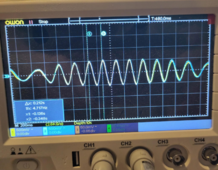
Why is waveform not uniform? Is rotational speed varying?
Now that you've got a full disk of magnets I expected a continuous sine wave of one frequency.
 

diy solar

diy solar
Back
Top