diy solar

diy solar

Design Review - Growatt SPF 5000 ES Grid Backup & Neutral Bonding

One caution,
I don't see a voltage or amperage rating for the dry contact in the specs sheet or manual.
The amperage needed to activate the coil is likely a few (or hundred) milliamps, so probably not a problem.
Voltage limit of the contacts is unknown.

Is the side of the contact accessible to read the specs or part number off of the module itself?
@Desert_AIP I am not sure what model I will be using for that contactor yet, I need to dig into how the dry contacts work and then pick a contactor to suit. I just picked a picture of something I thought may be close. It needs to be sized to carry the load in the event of a fault. So Probably something in the 50A range.

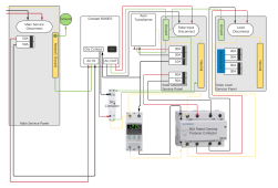
@LeRoyK Is this what you were talking about? Does this appear to be a complete wiring schematic for a safe circuit with these units?

Wiring for Growatt 5000ES with Neutral  disconnect and Ground Bonding.png
 
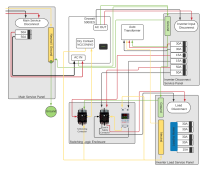
Thanks all for the work on this - I edited @automatikdonn 's lucidchart file from post #62 ? with the following changes:
  • Changed 'Solar Disconnect Service Panel' name to 'Inverter Disconnect Panel'
  • Changed 'Solar Load Service Panel' name to 'Inverter Load Service Panel'
  • Changed '60A Rated General Purpose Contactor' to a generic 120V coil, 2P NO contactor (yes, this would need to be paralleled to go from the 30A rating to a 60A rating which is not super elegant). Also I don't think it's necessary to switch the neutral of the 'Inverter Load Service Panel' here
  • Changed ground for inverter loads to be in 'Inverter Disconnect Service Panel' instead of through the GW itself

    conditional_neutral_bond-png.70763
Summary of features:
  • 'Inverter Disconnect Panel' disconnects L1/L2 in the event that the AT does not form 120V +/- (TBD tolerance) on one of the 120V legs
  • G/N bond within 'Inverter Load Service Panel' is open when on grid power and closed (bonded) when on backup power
Here's the GW 5000 ES manual for the dry contact state when setting 24 is enabled. For reference, 'line mode' is 'utility mode'. We'd connect between 'NO' and 'C' (COM), which closes when we lose grid input (according to the manual):
1635620058126.png
And here's setting 24, for reference - we'd want it 'enable' for our proposed use case:
1635620198885.png


Problems / Questions:​

  • Using two 2P 30 or 40A contactors to switch the Inverter Load Service Panel is not super elegant. Plus side is these contactors are cheap and UL listed.
  • Just for clarity - this configuration handles a ground fault (from within the Inverter Load Service Panel) when in on-grid mode by using the Main Service Panel's G/N bond to clear the fault - is that correct? If so - if we had a ground fault on the Inverter Load Service Panel (say, on a 15A single pole breaker), we'd have three CBs along the fault path:
    • 50A double-pole in the Main Service Panel (feeding the GW)
    • 50A double-pole in the Inverter Disconnect Service Panel (feeding the Inverter Load Service Panel)
    • 15A single-pole in the Inverter Load Service Panel (feeding the faulted 120V load)
  • According to the manual for a similar overvoltage protection relay - it looks like the power-on time for the load is adjustable from 2-255s (default 2), which is great news because this gives us a 2s delay to allow our AT neutral to a) switch and b) fully stabilize before we turn on the 120V loads panel (Inverter Load Service Panel)
 

Attachments

  • conditional_neutral_bond.png
    conditional_neutral_bond.png
    284.6 KB · Views: 411
Last edited:
I am working on getting all of the parts in still. I'm using UL listed components where possible.

I think you chart looks great. I don't have any holes I can poke in the model.

I will post up a full parts list when I get everything up and running.
 
A quick question about the circuits in the inverter load service panel (the ones going out to the louds in the house). If these circuits are brought over from the main service panel, how do you wire the neutrals? Do you bring both hot and neutral over to the breaker in the inverter load service panel or just the hot? If the latter, what do you do with the neutrals? I have in mind this video from Johnny Valentine. I know he his working with a Sol-Ark, so this is not a direct comparison, but I'm just wondering what the best practice would be for the Growatt-Auto Transformer system discussed in this thread.
 
A quick question about the circuits in the inverter load service panel (the ones going out to the louds in the house). If these circuits are brought over from the main service panel, how do you wire the neutrals? Do you bring both hot and neutral over to the breaker in the inverter load service panel or just the hot? If the latter, what do you do with the neutrals? I have in mind this video from Johnny Valentine. I know he his working with a Sol-Ark, so this is not a direct comparison, but I'm just wondering what the best practice would be for the Growatt-Auto Transformer system discussed in this thread.
If I am understanding your question correctly, the answer is nothing is pulled directly from service mains into inverter load service panel. It flows from mains service through the inverter chain. So you neutral is still provided by the auto transformer.

You could pull it directly over, but you would need to have a switch. Also charging the battery would no longer be possible because you would be skipping the inverter A/C input.

It's possible I'm not understanding the question correctly though.
 
A quick question about the circuits in the inverter load service panel (the ones going out to the louds in the house). If these circuits are brought over from the main service panel, how do you wire the neutrals? Do you bring both hot and neutral over to the breaker in the inverter load service panel or just the hot? If the latter, what do you do with the neutrals? I have in mind this video from Johnny Valentine. I know he his working with a Sol-Ark, so this is not a direct comparison, but I'm just wondering what the best practice would be for the Growatt-Auto Transformer system discussed in this thread.
For the loads you want powered on the inverter panel. You need to bring over both hot and neutral.
Even if that is a pigtail wire nutted in the main panel and brought over to the inverter panel.

With AC, both the hot and neutral are current carrying, with alternate phases.
You need to bring the pair of hot and neutral over in the same conduit so the magnetic fields generated by the current carrying conductors cancel each other.
If you only bring over the hots, the magnetic field from that single current carrying conductor will not be cancelled and will induce currents in any metal object the wire passes through. (Conduit, service panel, metal junction box).

Current moving through a wire generates a magnetic field.
A wire moving through a magnetic field generates a current.
The rising and falling magnetic field, with reversing polarity, creates a moving magnetic field, and a static wire will generate a current because the magnetic field itself is moving.
 
Last edited:
Thanks all for the work on this - I edited @automatikdonn 's lucidchart file from post #62 ? with the following changes:
  • Changed 'Solar Disconnect Service Panel' name to 'Inverter Disconnect Panel'
  • Changed 'Solar Load Service Panel' name to 'Inverter Load Service Panel'
  • Changed '60A Rated General Purpose Contactor' to a generic 120V coil, 2P NO contactor (yes, this would need to be paralleled to go from the 30A rating to a 60A rating which is not super elegant). Also I don't think it's necessary to switch the neutral of the 'Inverter Load Service Panel' here
  • Changed ground for inverter loads to be in 'Inverter Disconnect Service Panel' instead of through the GW itself

    conditional_neutral_bond-png.70763
Summary of features:
  • 'Inverter Disconnect Panel' disconnects L1/L2 in the event that the AT does not form 120V +/- (TBD tolerance) on one of the 120V legs
  • G/N bond within 'Inverter Load Service Panel' is open when on grid power and closed (bonded) when on backup power
Here's the GW 5000 ES manual for the dry contact state when setting 24 is enabled. For reference, 'line mode' is 'utility mode'. We'd connect between 'NO' and 'C' (COM), which closes when we lose grid input (according to the manual):
View attachment 70760
And here's setting 24, for reference - we'd want it 'enable' for our proposed use case:
View attachment 70761


Problems / Questions:​

  • Using two 2P 30 or 40A contactors to switch the Inverter Load Service Panel is not super elegant. Plus side is these contactors are cheap and UL listed.
  • Just for clarity - this configuration handles a ground fault (from within the Inverter Load Service Panel) when in on-grid mode by using the Main Service Panel's G/N bond to clear the fault - is that correct? If so - if we had a ground fault on the Inverter Load Service Panel (say, on a 15A single pole breaker), we'd have three CBs along the fault path:
    • 50A double-pole in the Main Service Panel (feeding the GW)
    • 50A double-pole in the Inverter Disconnect Service Panel (feeding the Inverter Load Service Panel)
    • 15A single-pole in the Inverter Load Service Panel (feeding the faulted 120V load)
  • According to the manual for a similar overvoltage protection relay - it looks like the power-on time for the load is adjustable from 2-255s (default 2), which is great news because this gives us a 2s delay to allow our AT neutral to a) switch and b) fully stabilize before we turn on the 120V loads panel (Inverter Load Service Panel)
This diagram looks great to me!
I was planning on running the Hot wire from breaker thru dry contact instead of the neutral wire like you do, but this will work just as well.
Not that it matters, but I always put my switches on the Hot wire, is there any special reason why that you are switching the Neutral wire with the Dry Contact?
 
The only thing I think I am going to add are some fire safety shutdown circuits to this design. These inverters are not listed and the components required are difficult to find that are UL, so every measure possible must be taken to keep them from burning down my shop. I am open to ideas and thoughts around how this could be accomplished.

I am not sure if I should start a new thread or not.
 
Thanks all for the work on this - I edited @automatikdonn 's lucidchart file from post #62 ? with the following changes:
  • Changed 'Solar Disconnect Service Panel' name to 'Inverter Disconnect Panel'
  • Changed 'Solar Load Service Panel' name to 'Inverter Load Service Panel'
  • Changed '60A Rated General Purpose Contactor' to a generic 120V coil, 2P NO contactor (yes, this would need to be paralleled to go from the 30A rating to a 60A rating which is not super elegant). Also I don't think it's necessary to switch the neutral of the 'Inverter Load Service Panel' here
  • Changed ground for inverter loads to be in 'Inverter Disconnect Service Panel' instead of through the GW itself

    conditional_neutral_bond-png.70763
Summary of features:
  • 'Inverter Disconnect Panel' disconnects L1/L2 in the event that the AT does not form 120V +/- (TBD tolerance) on one of the 120V legs
  • G/N bond within 'Inverter Load Service Panel' is open when on grid power and closed (bonded) when on backup power
Here's the GW 5000 ES manual for the dry contact state when setting 24 is enabled. For reference, 'line mode' is 'utility mode'. We'd connect between 'NO' and 'C' (COM), which closes when we lose grid input (according to the manual):
View attachment 70760
And here's setting 24, for reference - we'd want it 'enable' for our proposed use case:
View attachment 70761


Problems / Questions:​

  • Using two 2P 30 or 40A contactors to switch the Inverter Load Service Panel is not super elegant. Plus side is these contactors are cheap and UL listed.
  • Just for clarity - this configuration handles a ground fault (from within the Inverter Load Service Panel) when in on-grid mode by using the Main Service Panel's G/N bond to clear the fault - is that correct? If so - if we had a ground fault on the Inverter Load Service Panel (say, on a 15A single pole breaker), we'd have three CBs along the fault path:
    • 50A double-pole in the Main Service Panel (feeding the GW)
    • 50A double-pole in the Inverter Disconnect Service Panel (feeding the Inverter Load Service Panel)
    • 15A single-pole in the Inverter Load Service Panel (feeding the faulted 120V load)
  • According to the manual for a similar overvoltage protection relay - it looks like the power-on time for the load is adjustable from 2-255s (default 2), which is great news because this gives us a 2s delay to allow our AT neutral to a) switch and b) fully stabilize before we turn on the 120V loads panel (Inverter Load Service Panel)
Finally I found a UL Listed Contactor that is pretty close in meeting the requirements - however it is not cheap.

https://www.mcmaster.com/9114T362/
120V Contactor
Switching Current @ 600V AC
Full Load50A
Resistive Load55A

240V Contactor (Could be used to wire in a genset to the input side of the Inverter) - https://www.mcmaster.com/9114T363/

I am still searching for the voltage protection relays that are UL listed.
This contactor may work, a bit better price.

CWB50-11-30D15

 
Great work - I'm going to try to polish up the wiring diagram a bit this week before my lucidchart trial expires.

Re: Contactors:
  • Ya'll may have better luck finding a 2 pole contactor instead of a 3 pole. Also, the ones ya'll linked are 50A, and I believe we'd need 50A * 1.25 = 63A rating on the poles to be able to trip the 50A CB upstream in the 'Inverter Load Disconnect Panel'.

Re: Fire safety:
  • PV Shutdown: I'm semi-familiar with NEC Article 690, which requires rapid PV shutdown if your array is roof-mounted (690.12). Tigo TS-4 RSS is the only inverter-agnostic solution that would work with the GW and be compliant. Setup would be just like this. Ground-mount arrays are less stringent.
  • Labeling: Since we've got three power sources (Grid, PV, BAT), we'll need to comply with 710.10 labeling ("CAUTION: MULTIPLE SOURCES OF POWER).
  • Disconnecting means:
    • PV: 712.34 requires LOTO capability of PV source - IMO switches like this have a hole for that cause.
    • AC: 712.35 says we need to be able to disconnect all poles of ungrounded conductors, and as far as I am concerned, the 50A double pole DB in our service panel to the AC IN of the GW satisfies that requirement.
    • BAT: Not sure just yet
General rear-covering:
  • Right now we haven't tested overtemp faults for the GW, nor do we have temp monitoring on the autotransformer (it comes with a thermocouple, I believe). Those may be good next steps.
  • De-energizing the system with mechanical failsafes I think are always good. Normally-open contactors do a great job of that, and that's why I'm using them for the neutral safety circuit. The Tigo TS-4 'fails safe' as well. Only remaining energy source is the battery - I think I'd consider using a 2 pole contactor for this with a 240VAC coil. This way, the battery powers the inverter, which in turn holds the coil closed. If the inverter ever stops putting out 240VAC, the battery 'fails open'. There's a mechanical button on contactors to manually actuate the solenoid internally, which forces a human-in-the-loop for cold-starting the system (which I think is kinda elegant)
Hey I really like where you are going with the general rear covering section. Also with lucidchart I do believe you can keep using it for free. It just limits the number of total objects a chart can have.
 
I bought a Growatt 5000 and SolarEdge AT as well but have been troubled by the issues brought up in David's video/comments. I think someone already brought up this question: with the added costs of the SolarEdget AT, and all the components necessary to make this safe, do you still think this is right solution vs just buying another All-In-One that outputs 5kW or 6kW in 120v/240v split phase ?
I don't have much experience with electricity, so was searching for someone who's found the solution.. which led me to this thread

my goal for solar powered inverter is to run the well pump and septic systems in 240v, water softener, booster pump, some septic aerators, well house and garage lights on 120v
Like you most of my powered loads are 240, so I think this inverter is a good fit. That said there is a small amount of complexity into making the unit safe to use for the OP's original use case.

Do you have the same case?
Half of the complexity is the grid assist auto bonding.

We are pretty close to a parts list so we can make this easy for everyone.

I also plan to setup a video to walk through how it all works.

I'm just waiting on parts to be delivered at the moment
I think the same case.. except I don't want solar first. I want to use SBU setting: solar, battery, utility in order of priority. This should be the same wiring as OP, right? just a software setting/priority difference. I also have 2 different buildings with 120/240 loads: a well house/pump and a garage/septic, so not sure to put a Growatt/AT in each building/subpanel or to build a separate shed to house Growatt/AT at the main subpanel (which feeds the 2 buildings).
 
I think the same case.. except I don't want solar first. I want to use SBU setting: solar, battery, utility in order of priority. This should be the same wiring as OP, right? just a software setting/priority difference. I also have 2 different buildings with 120/240 loads: a well house/pump and a garage/septic, so not sure to put a Growatt/AT in each building/subpanel or to build a separate shed to house Growatt/AT at the main subpanel (which feeds the 2 buildings).
I have been tinkering around with the idea of a "power building" myself. Right now my test rig is all set up in the shop, but I guess my logic should be centered around the unhappy path of any solar setup. What happens in a malfunction and what do I have to lose? For my case, I have waited my whole life to have a real shop (complete with vertical machining center) - so I will likely be looking at methods to lower the damage in a total system failure.

If you place multiple systems in multiple buildings, then you have less 240 split phase to run. In my opinion this is the easiest part of the system to work with, so I plan to centralize all of my power gen equipment in one location.

My plans are similar to yours, but I have a genset thrown into the mix to deal with as well. My priorities are Solar first, Battery, Utility, then emergency power. I think the purpose of this thread is to work out safe circuitry for the Growatt 5kES with an auto transformer- power priorities aside it should all work just about the same.
 
I bought a Growatt 5000 and SolarEdge AT as well but have been troubled by the issues brought up in David's video/comments. I think someone already brought up this question: with the added costs of the SolarEdget AT, and all the components necessary to make this safe, do you still think this is right solution vs just buying another All-In-One that outputs 5kW or 6kW in 120v/240v split phase ?
I don't have much experience with electricity, so was searching for someone who's found the solution.. which led me to this thread

my goal for solar powered inverter is to run the well pump and septic systems in 240v, water softener, booster pump, some septic aerators, well house and garage lights on 120v

If you have many inductive loads such as multiple motors, Growatt staff recommend the SPF 6000 / 12000T DVM-MPV inverter.
It is special for when there are a lot of electric motors
Directly comes with split phase (two phases and a neutral)
Its disadvantage is its weight and its efficiency compared to the SPF 5000 ES
Next its technical specifications
 

Attachments

  • Growatt SPF 6000T-12000T DVM-MPV.pdf
    1.6 MB · Views: 48
  • Growatt SPF 6000T-12000T DVM-MPV.pdf
    1.6 MB · Views: 29
  • Like
Reactions: lns
If you have many inductive loads such as multiple motors, Growatt staff recommend the SPF 6000 / 12000T DVM-MPV inverter.
It is special for when there are a lot of electric motors
Directly comes with split phase (two phases and a neutral)
Its disadvantage is its weight and its efficiency compared to the SPF 5000 ES
Next its technical specifications
I think we all can agree that there may be better choices for inverter. Many of them are already UL, so we wouldn't be having any of this conversation. I think we are really just having some enginerding fun solving the david poz conundrum.

I think this is probably going to be the best thing out there - https://www.mppsolar.com/v3/catalogs/LVX6048WP.pdf
 
Last edited:
  • Like
Reactions: lns
Back
Top