diy solar

diy solar

Deye 5k Hybrid zero export to ct issue

I paralleled the cores up. I.e 4 wires for each of the CT conductors.
I am sure this is not how to use Twisted Pair cables.
You should use only 1 pair, and use Pure Copper (not Copper Coated Aluminum) as it needs to conduct as much as 1A.

Better result is to use Shielded Twisted Pair: each pair is shielded
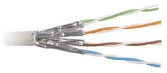
1680480286958.jpeg


Best result is to use Double Shielded Twisted Pair: each pair is shielded, and then the whole pack is shielded again.
images
 
I am sure this is not how to use Twisted Pair cables.
You should use only 1 pair, and use Pure Copper (not Copper Coated Aluminum) as it needs to conduct as much as 1A.

Better result is to use Shielded Twisted Pair: each pair is shielded
View attachment 142632


Best result is to use Double Shielded Twisted Pair: each pair is shielded, and then the whole pack is shielded again.
images
Obviously twisted pair cable is for carrying high frequency data signals and it's twisted to minimise signal interference.

We are using it to carry a CT secondary current here. A very different scenario, which is far less susceptible to crosstalk.
The additional current carrying capacity of having 4x23AWG (equivalent to 1mm^2 or 17AWG) in parallel is far more beneficial to having the conductors properly twisted.

The reason CT extension cable is twisted is to reduce the impedance of the cable by adding a small amount of inductance to cancel out the capacitance of the cable.
Since impedance is primarily made up of resistance for 50Hz signals, then reducing the resistance of the conductor by paralleling up cores is going to be much more beneficial to reducing the load on the CT and therefore avoiding it going into saturation.

There might be a slight advantage to having shielded cable, but in most cases it would be a waste of money.

The proper cable to use would be 600V rated 1 or 1.5mm^2 cable, ideally circular (twisted) rather than flat (parallel) cable.
600V is a good idea because the cable will be installed in main switchboards, and will be run near other LV power cables.
 
I extended my ct cable using cat 6. I paralleled the cores up. I.e 4 wires for each of the CT conductors.

Total length would be about 20-30m.

It works perfectly for me. I actually had a Chint smart meter but that has been giving me problems with having a wildly oscillating current reading when actual current flow is close to zero.
The CT is rock solid.

CT cables can be extended. It isn't necessarily a weak signal, it's a small current that flows. The limiting factor is the VA rating of the CT itself. If the cables have a high impedance (long and small CSA) then the CT might get overloaded and the reading will be unreliable, particulalry when the current is high. So if you want to extend the CT wires, use a larger conductor to reduce load on the CT (called burden).
Hi Thank you for your advice. Do you have experience with place the CT sensor connected, use wireless ?
 
Hi Thank you for your advice. Do you have experience with place the CT sensor connected, use wireless ?
No. Not possible with a CT.
Theoretically possible with a smart meter and a wireless rs485 bridge, but I don't think it's a good idea.
 
Back
Top