diy solar

diy solar

EG4 18KPV - What not to do in parallel

Since it works exactly as advertised correctly cabled. I can vouch that I was not aware of this particular issue. Not sure what the issue is when there isn't one.
Well I wouldn’t ask you to put in a Crossover cable to verify but that would concern me somewhat.
 
Yes they did, manual revision number went from 2.2 to 2.2.1. I got the new manual from sig solar. Refreshing didn’t work for me (ipad).
Ipad here too.

Lay money they never checked eg4 6000xp made by LuxPower too. That manual is not updated to reflect the same for cable. Proactive or retroactive. Be what it be.

UL labelling use to require failed in predictable safe manner but with so much from China as goods not true lab tested …. Expect things to be missed.

For safety and CYA think EG4 should update 6000xp manual. They have plenty of ppl just for these things - issues and accepted them when their name went on. 😁
I am sure they are on it.
 
  • Like
Reactions: D71
Just a guess but if Luxpower made eg4 18kw and eg4 6000xp my guess is it needs to be checked for same over sight.

In aviation a safety of flight like high profile recall would be performed. An attempt to contact all owners would be done to warn and aircraft might be grounded - no flights until repair TB had been accomplished…. to resolve.

I was sent a new Air Fryer…because of recall. The old one had to have the cord cut off and pictureS sent to get replacement.

I would think these units can be resolved with software - firmware. Again would be interesting to venture bet if 18kw and 6000xp behave in likewise manner. It is EG4 responsibility to check them and issue warning.

If I paid someone to install a system and stuff got destroyed by over voltage would be upset. If did it myself and installed a component not matched as exact replacement then would issue myself as partial blame.

View attachment 218666

View attachment 218667


EG4 18kw manual

View attachment 218668

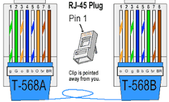
I am in the T568B camp, your T568A diagram is confusing me. :p:ROFLMAO::LOL:
 
OP was just trouble shooting a very nice install, which followed all procedures in manual and still fried some appliances, DERP!
!This is not accurate! The person who installed did not follow all the procedures in the manual and did not use the factory provided cable which is clearly labeled. The manual has no specifics listed on the interconnect cable, thus unlike *ME* the installer did not verify the cable pinout before substituting it with a different cable. Since the installer decided to use some random ethernet cable that happened to be a crossover it created an unusual fault condition that was not detected by the firmware, nor anticipated by the manufacturer. I would hold a manufacturer liable if they don't correct the documentation with a warning once they see the deficiency. If possible I expect a firmware or simple hardware fix to prevent this condition as quickly as possible now that the problem is identified. I would expect future revisions of the product to not allow this behavior.

If someone accidentally mis-wires something I built and it causes a problem I'm not the one who screwed up. Not too long ago, I inadvertently plugged a 110v/220v power supply into a 220 without moving the physical switch. I got magic smoke it blew up and took out something plugged into it. Not the manufacturers fault, it was mine.

This discussion is interesting because people keep intimating the "Professional" installer did everything right and somehow everything blew up. This is not what happened. The installer made a mistake, and it seemed to be working but his error caused the equipment to behave in an unexpected manner under some conditions.

It needs to be addressed for the future but the error was done by the installer.

I totally get what you're saying, but the installer did not violate the installation instructions per yesterday's manual.
 
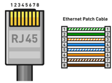
We have already updated the manual to show the necessary pinout of the parallel cable. We will be making this accessible in all our manuals for equipment that have cables to alleviate any sort of confusion. The photo below will be attached to all paralleling guides moving forward.

straightthroughpinout.png


When inverters or other units are sent in for UL Testing/Certification, you have to send in the installation manual. They test the inverter to make sure that it works as advertised when following the specifications of the manual. They test the inverters rigorously, and make sure that the proper error codes are thrown. I don't personally know if they test cross-over cables, but in this case specifically, the paralleling cable was a cross-over cable, and was not what was provided. It's an easy mistake to make, but that is why we will make sure that information is always available moving forward.

I am making all of the information from the previous thread available to our engineering team as well. We will be testing and working to find ways to mitigate any sort problems from using improper communications between inverters so that situations like this no longer arise.

I appreciate the time, effort, and work that went into solving this issue by everyone here in the forum, and the information that @automatikdonn and @canadianintruder made available to everyone here in the forum and the EG4 team.
 
Wait..

@EG4_Jarrett

Do these cables need to be on the T568A standard? Is the T568B standard acceptable?

This is an actual question? If the answer is follow the manual, then I am making new ends for @canadianintruder system tonight after work.
It’s just the coloring of the cables, no effect electrically as long as both ends are the same and straight through.
 
We have already updated the manual to show the necessary pinout of the parallel cable. We will be making this accessible in all our manuals for equipment that have cables to alleviate any sort of confusion. The photo below will be attached to all paralleling guides moving forward.

View attachment 218684


When inverters or other units are sent in for UL Testing/Certification, you have to send in the installation manual. They test the inverter to make sure that it works as advertised when following the specifications of the manual. They test the inverters rigorously, and make sure that the proper error codes are thrown. I don't personally know if they test cross-over cables, but in this case specifically, the paralleling cable was a cross-over cable, and was not what was provided. It's an easy mistake to make, but that is why we will make sure that information is always available moving forward.

I am making all of the information from the previous thread available to our engineering team as well. We will be testing and working to find ways to mitigate any sort problems from using improper communications between inverters so that situations like this no longer arise.

I appreciate the time, effort, and work that went into solving this issue by everyone here in the forum, and the information that @automatikdonn and @canadianintruder made available to everyone here in the forum and the EG4 team.

Excellent response. Good on you guys.
 
!This is not accurate! The person who installed did not follow all the procedures in the manual and did not use the factory provided cable which is clearly labeled. The manual has no specifics listed on the interconnect cable, thus unlike *ME* the installer did not verify the cable pinout before substituting it with a different cable. Since the installer decided to use some random ethernet cable that happened to be a crossover it created an unusual fault condition that was not detected by the firmware, nor anticipated by the manufacturer. I would hold a manufacturer liable if they don't correct the documentation with a warning once they see the deficiency. If possible I expect a firmware or simple hardware fix to prevent this condition as quickly as possible now that the problem is identified. I would expect future revisions of the product to not allow this behavior.

If someone accidentally mis-wires something I built and it causes a problem I'm not the one who screwed up. Not too long ago, I inadvertently plugged a 110v/220v power supply into a 220 without moving the physical switch. I got magic smoke it blew up and took out something plugged into it. Not the manufacturers fault, it was mine.

This discussion is interesting because people keep intimating the "Professional" installer did everything right and somehow everything blew up. This is not what happened. The installer made a mistake, and it seemed to be working but his error caused the equipment to behave in an unexpected manner under some conditions.

It needs to be addressed for the future but the error was done by the installer.

The factory cable wasn't long enough. I don't know how you could follow the spacing requirements and have it be long enough and still be in the raceway.

The units should never have went into parallel mode. They should have reported communications wasn't proper and stayed in error state.

An inverter should under NO CONDITION send 400v+ back to the grid.
So you are saying there is zero culpability, but I don't think that is accurate.

Is the installer wrong - YES
Are the inverters doing things they shouldn't - YES

They don't have to be mutually exclusive.
 
We have already updated the manual to show the necessary pinout of the parallel cable. We will be making this accessible in all our manuals for equipment that have cables to alleviate any sort of confusion. The photo below will be attached to all paralleling guides moving forward.

View attachment 218684


When inverters or other units are sent in for UL Testing/Certification, you have to send in the installation manual. They test the inverter to make sure that it works as advertised when following the specifications of the manual. They test the inverters rigorously, and make sure that the proper error codes are thrown. I don't personally know if they test cross-over cables, but in this case specifically, the paralleling cable was a cross-over cable, and was not what was provided. It's an easy mistake to make, but that is why we will make sure that information is always available moving forward.

I am making all of the information from the previous thread available to our engineering team as well. We will be testing and working to find ways to mitigate any sort problems from using improper communications between inverters so that situations like this no longer arise.

I appreciate the time, effort, and work that went into solving this issue by everyone here in the forum, and the information that @automatikdonn and @canadianintruder made available to everyone here in the forum and the EG4 team.
Please update the manual to include both T-568A (as shown) and T-568B. Both are straight through with the green/white and green swapped with the orange/white and orange. Either cable will work but someone looking at the ends may reject a perfectly good T-568B cable

RJ45_Connector_Pinout.png
 
Well I wouldn’t ask you to put in a Crossover cable to verify but that would concern me somewhat.
I played around a number of times with various configurations when I first got the units and got them in parallel. They won't feed the grid if only one of the two has grid either. I leverage this to keep them in sync. It also fails comm if you use the wrong provided cable. Perfect storm.
 
I am not will to take that chance.
Our manuals will show T568A pinouts going forward. I understand that the cable wasn't long enough. That's why we are adding that pinout to the manual so that if the need arises, you have a formula to follow. T568B will also work, since it's a straight through pinout as well. So long as you are not crossing pins, there will be no issue.
An inverter should under NO CONDITION send 400v+ back to the grid.
So you are saying there is zero culpability, but I don't think that is accurate.

Is the installer wrong - YES
Are the inverters doing things they shouldn't - YES
I am making all of the information from the previous thread available to our engineering team as well. We will be testing and working to find ways to mitigate any sort problems from using improper communications between inverters so that situations like this no longer arise.
 
@EG4_Jarrett Would it be possible to get the pinout of what pin does what inside the parallel connectors? If possible I would like to run this to the ground. A crossover cable shouldn't have allowed the inverters to even communicate. Maybe you guys are already working that, but it would be awesome to have a full RCA on this issue.
 
Just a guess but if Luxpower made eg4 18kw and eg4 6000xp my guess is it needs to be checked for same over sight.
Yes they are the same manufacturer but they are very different units. However well worth testing now.
 
  • Like
Reactions: D71
Our manuals will show T568A pinouts going forward. I understand that the cable wasn't long enough. That's why we are adding that pinout to the manual so that if the need arises, you have a formula to follow. T568B will also work, since it's a straight through pinout as well. So long as you are not crossing pins, there will be no issue.
The factory cable wasn't long enough. I don't know how you could follow the spacing requirements and have it be long enough and still be in the raceway.

The units should never have went into parallel mode. They should have reported communications wasn't proper and stayed in error state.

An inverter should under NO CONDITION send 400v+ back to the grid.
So you are saying there is zero culpability, but I don't think that is accurate.

Is the installer wrong - YES
Are the inverters doing things they shouldn't - YES

They don't have to be mutually exclusive.
I have known over 13 years of using solar inverters that if you use your own ethernet cable weird things will happen. Outback, Schneider, magnum to name a few
 
Dude it happened! These have not been out that long. It will happen again. As per my previous post, imagine 3 of them connected up with the twisty cables unknowingly. The cables supplied are too short for a lot of installs. It will happen again if not "fixed". OP was just trouble shooting a very nice install, which followed all procedures in manual and still fried some appliances, DERP!
I'd love to see 4 units in parallel with crossover cables. I have several of them lying around, even after going through a shop rehab and overall organizing. This thread actually reminded me that I mixed all my ethernet cables into the same big bin for later use...
Yes there should be different length cables or one really long cable included. And labeled. And mentioned in the manual.
 
I have known over 13 years of using solar inverters that if you use your own ethernet cable weird things will happen. Outback, Schneider, magnum to name a few
I do agree however. Most manuals, but not all (and not for all connectors/jacks) provide the connector pinout and what signal (TX, RX, RS485A, RS485B, CAN-L, CAN-H) is on each pin. Many RJ45 connectors include both CAN and RS485 and some include power or a combination of any of these.

Many Inverter RJ45 connectors using RS485 use pins 7&8 on the inverter end with pins 1&2 on the BMS end. A simple CAT5 straight through cable will not work as pin 7 on the inverter end needs to go to pin 1 on on the BMS end, pin 2 on the inverter end needs to go to pin 8 on the BMS end.
 
Yes there should be different length cables or one really long cable included. And labeled. And mentioned in the manual.
One of those little plastic plugs could be inserted into the port at the factory, with a label on it secured by a plastic string, saying "DANGER, only use properly configured straight through ethernet cable or death may occur." :p
 

diy solar

diy solar
Back
Top