timselectric
If I can do it, you can do it.
- Joined
- Feb 5, 2022
- Messages
- 18,766
Yesok, but if the grid is connected to the ac input, then the NGB screw should be removed from all the inverters?
And a common neutral should be used.
Yesok, but if the grid is connected to the ac input, then the NGB screw should be removed from all the inverters?
awesome....i'm totally clear now. thanks much!
awesome....i'm totally clear now. thanks
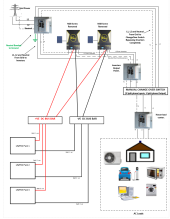
Not sure I follow. The chassis of the panels and inverters are grounded but just not bonded to neutral. I labelled them but didn't show the ground. I'm so glad I sent this diagram because I thought I had this correctActually I just realized that you are missing a lot of grounding. You don't show any grounding for the main panel, inverters, and combiner panel.
Ok. I'll update my diagram and resend just to make sure that I have it correct.Just move the ground rod connection and N/G bond to the main panel. If everything else is grounded (just not shown in the diagram) then you should be good.


One grounding system for everything.Ok. So here's the revised design. My question is this, the ground terminal on the EG4 6500 EX inverters, is that being connected to the same ground that is bonded to neutral or should a seperate ground be created for the inverters which is not bonded to any neutrals. Let me know if this design makes sense now. Also, please note that the NGB screw from both inverters are removed. Let me know if they should remain. Thanks again.
View attachment 137415
Thanks.Run an EGC from inverter input back to the main service panel. You can daisy chain them, or run the EGC to a busbar with a single wire back to main panel.
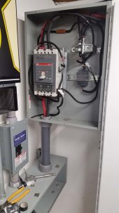
I like that you are using a 3 pole double throw so the inverters can be totally bypassed. That is how I did mine.
Ok great, thanks much.One grounding system for everything.
Everything is connected to the grounding system.
Otherwise looks good.


