diy solar

diy solar

EVE two-hole terminals (LF230, LF280, LF304)

abeness

New Member
Joined
Dec 1, 2022
Messages
22
I've been unable to find a CAD drawing of the EVE two-hole terminal. The spec sheets show the spacing of the positive and negative terminals, and I've seen the spacing of the terminal holes from positive to negative, but the center-to-center hole spacing of the terminal holes in one terminal has eluded me to date. Does anyone have this detail handy? I found two-hole NEMA lugs at Elec-Direct and elsewhere, and they come in 0.63- and 0.75-inch hole spacing.

EDIT: revise title for broader discussion.
 
Last edited:
That sounds pretty close to 0.63, as eyeballed at 11/16 (0.6875). If not a perfect fit at 0.0575 difference, I can always dremel it a wee bit to fit. Thanks, DIYrich.
 
I'm expanding this discussion to include EVE two-hole terminal contact options. I'm not excited by the limited surface area of the two-hole post as displayed on e.g. 18650batterystore for the LF230:
EVE two-hole terminal.png
That seems fine if you're going to use two-hole solid busbars across the full length of the terminal, in which case you use the full (albeit somewhat minimal) surface area.

But what if you don't want to use solid busbars because you know the cells are going to expand and contract with high current I/O and age, and you can't find suitable two-hole flexible busbars? eelbattery does make a single hole flexible version with 54mm spacing that would suite the single stud LF230, but maybe not the two-hole terminal.

I'm currently thinking that I'll just make my own series connections with 1/0 cable that I have left over, with quality tinned copper lugs (Ancor), and use 316 stainless steel grub screws for the best corrosion resistance I can work out in these aluminum terminals. I'm also considering aluminum threaded rod and aluminum serrated flange nut to achieve good contact from above, too. And there's copper braid.

I'm skeptical that the lug on a single SS stud on this abbreviated terminal surface will achieve adequate surface contact for 1C draw.

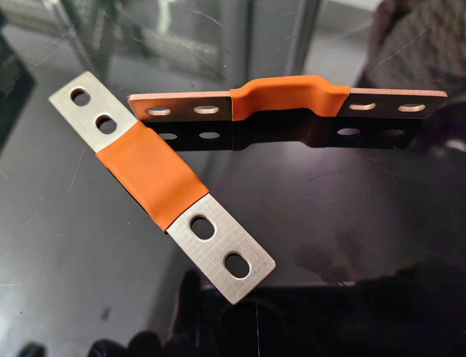
And so I'm starting to consider two-hole telecom lugs such as
BBLU4D2TC14_BBLU4_0D2TC14_109.png
(but I really would want one that does a right turn and haven't found that yet), or a segment of tinned copper bar stock cut and drilled to adapt full connection to the two-hole terminal, to e.g. a 5/16 bolt hole for single lug connection that would maximize contact.

Am I overthinking this? Would a single Ancor 1/0 x 1/4-in lug angled off the inner corner of this terminal afford adequate contact for 1C draw from e.g. an EVE LF230 cell? I suppose I could connect it to the "far" terminal--the one furthest from the cable exit direction, so the lug crosses towards the second hole. Now that I think further, maybe that's adequate contact area? This is just for a 4S 12V string, max draw expected maybe 160A, infrequently. I think I'm overthinking it...

I've seen mention of antioxidant paste, but I've read that there are different pastes for aluminum and for copper, and one should not be used with the other. What paste, if any, would be appropriate for a tinned copper and aluminum connection?
 
Another spec request: what is the actual depth, in mm, of the two-hole terminals? (This, too, is missing from the literature.)

I'm trying to plan the minimum stud length I need to fit the project.
 
I bought flexible busbars.

If you need to turn the corner, I found a square version on Alibaba.

The batteries I got came with studs. I don't think I can eyeball from the side to get the height.
 
Anyone else able to provide hole depth? Unfortunately, 18650batterystore has been unresponsive to email in the last few months.

DIYrich, I'll be using the LF230 cells, which are a different width than the LF280K. I was planning to build my own busbars out of 1/0 AWG that I have on hand, with lugs, going on a diagonal (with all cell +/- aligned the same way) to allow plenty of flex without terminal stress.

I can always measure after I receive the cells, and then buy the studs; it'll just add a few days to a project that is anyhow slow to develop...
 
Another spec request: what is the actual depth, in mm, of the two-hole terminals? (This, too, is missing from the literature.)

I'm trying to plan the minimum stud length I need to fit the project.
The two 6mm holes are tapped though the thickness of .375”(3/8 inch). Some terminals are Helicoiled but the fastener should still be able to thread through. It’s important to note that a grub/set screw will contact the top of the case at approximately .5” (1/2 inch) from the top of the terminal and risks penetrating the plastic insulation! Do I need to say that this would be very bad? There’s no advantage to the screw any deeper than 1/4” into the terminal. The screws can be stainless or zinc plating steel and same for the nuts. The set screws I use are 20mm long. The spacing between the holes in the terminal are .709” or 18 mm.
I highly recommend flexible buss bars. Many solid buss bars are not flat across the width (convex or concave) and don’t have good contact. I use NO-OX-ID “A” Special antioxidant for aluminum to tinned buss bars or lugs. Nothing with any metallic fillers. I don’t torque these terminals over 6Nm. Two short #2awg cables as shown equates the same resistance as a flexible buss for a jump across. A single hole Selterm or Ancor lug is for Output is plenty over kill. Do re torque the terminals in a few days and again in 6 months.
IMG_0890.jpeg
IMG_1234.jpeg
 
Thanks for all these spot-on notes, Skypower; and that's a beautiful build, thanks for the pics. Your 20mm studs look perfectly suited. I also see that you crimped together the positive BMS lead with the last balance lead, which I had a question about. What did you use between the cells?

When you report "spacing between the holes in the terminal are .709” or 18 mm", is that center-to-center?
You are correct the bms’s + power lead and the last balance lead are indeed crimped together. It’s just one less eye terminal, they had to go to the same place, the balance lead still has it’s own resistance and no chance of confusion( I don’t like the idea of sharing the same wire from the bms by using a short jumper at the connector). Yes that number is center to center. I used Formica between the cells because when I was looking for spacers there was none to be found. Now there’s a bunch of places like Eel battery, 18650 store and Amazon
 
Last edited:
You are correct the bms’s + power lead and the last balance lead are indeed crimped together. It’s just one less eye terminal, they had to go to the same place, the balance lead still has it’s own resistance and no chance of confusion( I don’t like the idea of sharing the same wire from the bms by using a short jumper at the connector). Yes that number is center to center. I used Formica between the cells because when I was looking for spacers there was none to be found. Now there’s a bunch of places like Eel battery, 18650 store and Amazon
I was considering those flexible cutting boards, or perhaps silicone baking sheets, then found sheets of Kapton tape with silicone adhesive for 3D printer beds (by Gizmo Dorks) that is just 1mil thick, with 1mil adhesive, that I plan to use for my metal end plates and other aluminum supports adjacent to cells. Comes in a 10-pack, so I’ll have plenty left for inter-cell insulation after the end plates are covered. These epoxy boards you linked are just 0.5mm thick. Cool. Not quite clear that they are fiberglass mat; others are.

I don’t think I’d jump at the connector either: I’d think voltage drop, however slight, could exist from power draw of the BMS, which would compromise that cell reading. Shared ring terminal makes much more sense.
 
I have also used this silicone between the cells but you have to use some kind of non corrosive talc or powder to keep it from trapping an air pocket, if you have a concave area on the side of the cell if you look carefully in the picture, I actually used one between the last cell and the wood pusher. https://a.co/d/2lg0Anm
In an ideal world a spacer consisting of a rigid plane ( 1.5 mill G10 epoxy glass) and compliant, resilient foam on each side of it would be preferred, but space and return of investment would be questionable. IMHO, just use the purchasable spacers and flexible buss bars with good fixturing practices and you’ll be way ahead of the rest.
 
Made lots of the damn things 😂
LOL. You should open an eBay store!

One question: It looks like you have (2) 7AWG wires in and out of your BMS, which is effective 4AWG. Why did you use 2/0 from the battery to the negative post? The Blue Sea Circuit Wizard reports 160A capacity for 4AWG over 1 foot, for reference, but 330A for 2/0. Your 2 x 2AWG jumper is basically 2/0 equivalent (67.2 mm2 while 2/0 is 67.4 mm2).
 
Again you are correct. Yes the two blues together equate to 4AWG and such a short distance that it’s consequential and impractical to upsize. They are the smallest part of the system and everything else is 2/0. It’s all about having the least voltage loss possible where practical. Also since I run multiple batteries, I know that the voltage and current available at each battery will be about as close as possible, so regardless of each battery’s quirks, they are going to play nice and follow. Yes the cables are over kill for most electrical situations, but when you are working between the inverter and battery, you pretty much throw the cable calculations out the window and go big. I can go down to two batteries and turn on the clothes dryer and there’s no, zip,nada blink in my lights because my voltage sag to the inverters are nil. If you are talking household/commercial/vehicle/marine, yes go with cable standards. A little voltage drop there doesn’t mean as much.
 
I've been unable to find a CAD drawing of the EVE two-hole terminal. The spec sheets show the spacing of the positive and negative terminals, and I've seen the spacing of the terminal holes from positive to negative, but the center-to-center hole spacing of the terminal holes in one terminal has eluded me to date. Does anyone have this detail handy? I found two-hole NEMA lugs at Elec-Direct and elsewhere, and they come in 0.63- and 0.75-inch hole spacing.

EDIT: revise title for broader discussion.

Though not an offical drawing, this is what the ali shops make of it...

1711268926555.png
1711268804471.png
 
Here is an official cad drawing from EVE for a 280K with studs. Come Monday I could probably get a copy of the drawings we did here when making a pack out of the cells. The datasheet with this drawing is now in the resources under EVE Datasheets part 2.
1711290865502.png
 
I can go down to two batteries and turn on the clothes dryer and there’s no, zip,nada blink in my lights because my voltage sag to the inverters are nil.
That's great. I aspire to running a clothes dryer off of a battery bank. Someday when I'm no longer an apartment dweller... In the meantime, just a 1500W hot water urn while camping.

Thanks for the drawings, zonnigBreda and zcskywire2. (It's still amazing to me that EVE doesn't include the hole spacing even in what is labeled as their internal info.)

And TomC4306, thanks for posting this Andy vid. His testing is very helpful: if those tiny-surface original welded studs barely heat up with 230A+ draw and a busbar that contacts only on two sides of the ring out of four, you're certainly correct that I don't need to overthink a connection to the broader two-hole terminal with a quality lug.
 
Back
Top