diy solar

diy solar

Extra/Auxilary grounding rods..... Don't do it.

View attachment 206197

I recommend routing the PV EGC directly to the main breaker box where the Grounding Electrode Conductor ties in. It would be better to route it directly to the grounding electrode, but I don't know if inspectors would allow it.
Ahh, that’s what it,was.

What about,adding an SPD? Then you can ground to the inverter.
Both of the above examples makes sense to me. But I also get not wanting to ground EGC from array to inverter. In other words I’m confused again, lol.

I was planning,to run each ECG seperately to one ground bus bar, and then to the 2 ground rods 8 feet apart
 
Isn’t that the same situation?
Yes and no. A ground rod is required at a 2nd building but not required at a ground mount array. Consequently, a ground rod at the array would be considered 'auxiliary' and there are no rules in the NEC to govern them. Grounding electrodes for the 2nd building are required and must follow the rules. One could argue this is an inconsistency in the code.
 
I was planning,to run each ECG seperately to one ground bus bar, and then to the 2 ground rods 8 feet apart
I like that idea but.......the code may not allow it. The code is rather picky about the connections to the grounding electrodes.

There may be rules in the NEC about either NO junctions or only permanent junctions (Cripmps or welds) in the grounding electrode conductor between the main breaker panel and the grounding electrodes. (I could be wrong about this.... I am going by memory).
 
What about,adding an SPD? Then you can ground to the inverter.

Adding an SPD is a good idea, but I would not change my recommendation for how to route the grounding based on whether there is an SPD installed or not.

The NEC is starting to require SPDs but I have not studied the code enough to understand the requirements.


BTW: Here is a question I don't have an answer for:

For the PV array, is it better to put the SPD close to the array or close to the grounding electrode?
On the one hand, putting it near the PV array would snub the pulse at the source.
On the other hand, the impedance of the EGC running from the array will reduce the effectiveness of the SPD.

I don't know what is best. Furthermore, it would be difficult to prove it one way or the other.

Midnite Solar solves the problem by recommending an SPD in both positions.... but I would say that too if I was selling $100 SPDs 😁
 
Midnite Solar solves the problem by recommending an SPD in both positions.... but I would say that too if I was selling $100 SPDs 😁
I took their advice and multiplied it. I’ve got one SPD per ground mount string before the combiner box (3 strings total).
And one SPD 220’ away where the PV and ground enter the house. Yes, i’m a little paranoid.
 
What’s the difference between 2nd , and auxiliary rods? 2nd would be 1 at house, and one at second building? Auxiliary would the the 2nd of 2 ground rods (connected together) forming the grounded electrode?
Auxiliary is any rod that is not required. (At signs, light pole, solar array)
Second or supplemental, is the second rod at a service to lessen the resistance to earth as a single contact point. And or the rod at a separate building. (While it's still required)
 
Also….. ground rod at array, and rod at main service is not a good idea….. but 2nd rod at 2nd building (let’s say detached garage sub panel is needed…….


Isn’t that the same situation?
Yes, it is the same situation.
But it's still currently required by the NEC.
Changes come slowly.
 
There may be rules in the NEC about either NO junctions or only permanent junctions (Cripmps or welds) in the grounding electrode conductor between the main breaker panel and the grounding electrodes. (I could be wrong about this.... I am going by memory).
Yes, that's correct.
The GEC must be a single unbroken conductor from the first means of disconnect to the electrode/s.
However it can connect to other points along the way, as long as it isn't broken (cut) to do so.
 
For the PV array, is it better to put the SPD close to the array or close to the grounding electrode?
Close to the SCC or AIO.
Because this is the equipment that we want to protect.
At the array, it only protects the array.
You can do both. But if only one, the equipment is more important.
 
I am not sure that for FilterGuy's examples above, where the voltage spike from the lightning is coming into the equipment over the ground wire, SPDs would help. MOVs are bi-directional devices, so if your SPD just has MOVs between your various lines and ground, the MOV is happy to "save" the ground line by passing that voltage spike over to the main lines.

Not how they are really supposed to work but ground is generally considered a sink for extra voltage spikes, except in this case where the spike is coming in on the ground lead. Not sure what sort of protection devices could really, when ground becomes the source of the spike instead of a place to dissipate it.
 
Yes and no. A ground rod is required at a 2nd building but not required at a ground mount array. Consequently, a ground rod at the array would be considered 'auxiliary' and there are no rules in the NEC to govern them. Grounding electrodes for the 2nd building are required and must follow the rules. One could argue this is an inconsistency in the code.
I don’t mean the same as per new, but functionally, or essentially the same? I.e array is like a sub panel in that you just run the 2 conductors and the ground. Same tith a sub panel for a garage. One receives power, one sends power but they both conduct electricity and both have an EGC. BUT…… one has to have a 2nd,ground rod but the other doesn’t HAVE have to have,a 2nd,rod (but is allowed).
 
I am not sure that for FilterGuy's examples above, where the voltage spike from the lightning is coming into the equipment over the ground wire, SPDs would help. MOVs are bi-directional devices, so if your SPD just has MOVs between your various lines and ground, the MOV is happy to "save" the ground line by passing that voltage spike over to the main lines.

Not how they are really supposed to work but ground is generally considered a sink for extra voltage spikes, except in this case where the spike is coming in on the ground lead. Not sure what sort of protection devices could really, when ground becomes the source of the spike instead of a place to dissipate it.
I have wondered about this as well. I don't have a great answer, but if the SPD clamps the lines together the voltage between various parts of the system should not jump too high. (It is the differential voltage that blows things out).
 
I don’t mean the same as per new, but functionally, or essentially the same? I.e array is like a sub panel in that you just run the 2 conductors and the ground. Same tith a sub panel for a garage. One receives power, one sends power but they both conduct electricity and both have an EGC. BUT…… one has to have a 2nd,ground rod but the other doesn’t HAVE have to have,a 2nd,rod (but is allowed).

Yes, they are essentially the same. I can't give a good reason for them being treated differently in the code. The most likely answer is that the people who work on the PV part of the code are not the same ones who work on the other parts of the code.

Having said that, in many cases, it is a distinction without a difference. Most ground mount arrays are grounded through the mounting system even if there is not a dedicated grounding electrode. Meanwhile, a 2nd building of any substance is likely to have pipes, rebar or other items that need to be grounded and they will create an earth ground.

Since unintentional earth grounding is a reality in many situations, I fall back on trying to rout the grounding wires in ways to try to prevent (or at least minimize) issues.
 
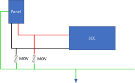
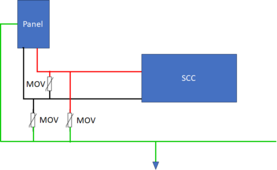
Since we are now talking about SPDs, There are One-way, Two Way and Three Way SPDs.

Most of the SPDs you seen in combinor boxes are two-way:

1711941539804.png

If there is a spike on either the positive or negative it gets shunted to ground.

However, the more complete solution is a three-way SPD:

1711941672257.png


With this a large spike between any two of the lines are shunted together.
 
The local electrical inspector required I put ground rods at each one of my ground mounts. It was the only electrical inspection I have ever failed. I also didn’t have the electrical conduit secured every three feet.
 
The local electrical inspector required I put ground rods at each one of my ground mounts. It was the only electrical inspection I have ever failed. I also didn’t have the electrical conduit secured every three feet.
Sad. :(
 
Since we are now talking about SPDs, There are One-way, Two Way and Three Way SPDs.

Most of the SPDs you seen in combinor boxes are two-way:

View attachment 206208

If there is a spike on either the positive or negative it gets shunted to ground.
I wonder what will happen in case of a non-isolated, floating AIO design in case of a surge event. Usually non of the PV+ or PV- is allowed to be connected to ground in such an AIO design. In case the MOV's (or one of them) will be activated, it will in fact connect the PV wire to ground. Will the FET's of the floating MPPT charger blow in such a situation?
If yes, could the surge protection be done different for a floating non-isolated charger? Maybe adding a (small resistor in series with the MOV to reduce the surge current in such a case)? But I think, this would only help a bit if the MOV's will switch back to high resistance after the surge is over... but I don't know.
A fuse at the charger side may help in such a case?
 
Back
Top