diy solar

diy solar

How to produce a significant Ground Fault?

burgerking

New Member
Joined
Apr 6, 2022
Messages
368
Location
Subic, Philippines
How much current to cause a significant Ground Fault ?
What is the best way to simulate one (on the PV wires, AC wires, Batteries)? (ie to cause an actual Ground Fault on a Deye Inverter for instance)
And what equipment best suited to detect them?
I want to train people on how to detect ground fault and therefore how to fix it.
 
The best way to produce one is simply a short, which can be catastrophic. If you want to produce a small one, dip two wires in a glass of water. Or anything in between..

In live systems the large ones will trip a breaker. The best way to detect small ones, including those between phase, neutral or positive, negative , is to measure the current difference between phase and neutral, or the current difference between positive and negative. The best way to detect them when the wires are disconnected is to use an Ohm meter for relatively large faults, or if you want to do it right a good quality insulation tester. With those you will have to disconnect any equipment that can't cope with high voltages before you start. You will have to know where in the circuit where to test it.

Be careful to protect your lungs, skin and eyes when creating faults and do it out in the open away from anything that can start a fire. Have a couple of electrical fire extinguisher on hand. Prepare for the worst when testing (as Will resently found out when he drilled into a battery)

A good place to start is to use your senses, smell, (electrical arc, insulation melting or burning), eyes, (glowing, discolouration, smoke) and ears, (arcing).

This is not a simple subject and you really need to teach beyond the basics of voltage, current and resistance for your students to grasp this. You might want an experienced electrician or better still, an experienced electrical engineer teach the students.
 
How much current to cause a significant Ground Fault ?
What is the best way to simulate one (on the PV wires, AC wires, Batteries)? (ie to cause an actual Ground Fault on a Deye Inverter for instance)
And what equipment best suited to detect them?
I want to train people on how to detect ground fault and therefore how to fix it.
A ground fault is defined as a short from a non-grounded conductor to the Grounding Circuit. The current could be quite high. On AC it can be as high as the protecting breaker allows.

On AC, a ground fault is 'cleared' by the high current popping the breaker ( One of the purposes of the Neutral-Ground bond is to provide a low impedance path so a ground fault creates the current needed to pop the breaker.

An AC GFCI breaker is used to clear a ground fault in situations where the current to the ground is much lower. In particular, it is designed to clear a ground fault that is going through a human. In the US, the typical GFCI will trip at something between 5ma and 7 ma. In europe the nearest equivelant is called a RCD (Residual Current device) and if I understand correctly, they can have trip values as high as 50ma. (50ma will give you a hell of jolt and can still kill)


PV ground fault protection requirements are different than on the AC side. On PV, the typical protection device will trip at .5A to 1A. These are put in for fire protection, but with the higher trip current they may not prevent electricution death.

A few documents you may want to read:


Assume house is supplied Split Phase power (120, Neutral, 120), and Inverter is non-split phase (Deye EU Version).

How does Inverters detect Ground Fault?
I assume Inverters simply detect current imbalance between L1 and L2?

And if that is the case, is it possible to generate a Ground Fault error by drawing power only L1 and Neutral?
 
Typically, household RCDs in Europe have 30mA trip point.
There are differences as well in types of RCD, some designed better to handle AC produced by inverters.

For testing in my home, I took a plug and inside it put a resistor of the appropriate value to get a leak current of a bit over 30mA between hot and ground.
 
How much current to cause a significant Ground Fault ?
What is the best way to simulate one (on the PV wires, AC wires, Batteries)? (ie to cause an actual Ground Fault on a Deye Inverter for instance)
And what equipment best suited to detect them?
I want to train people on how to detect ground fault and therefore how to fix it.
Forgive me for asking but if my instructor (for any subject) does not understand the subject, how can he teach it?
 
A GFCI breaker detects a mismatch between current on line and current on neutral.
It infers leakage to ground.

To demonstrate ground leakage, wire an led light between line and ground.

line->standard_breaker->switch->led_light->ground // if the light illuminates you have a n-g bond somewhere

line->gfci_breaker->switch->led_light->ground // gfci should trip when the switch is closed.
 
Last edited:
Forgive me for asking but if my instructor (for any subject) does not understand the subject, how can he teach it?
In the beginning, nobody knew much of anything, on any subject. At least he is asking and trying to learn. He lives in the Philippines. We have no idea what kind of conditions he lives in and access to what sort of training schools he has.
 
In the beginning, nobody knew much of anything, on any subject. At least he is asking and trying to learn. He lives in the Philippines. We have no idea what kind of conditions he lives in and access to what sort of training schools he has.
I wouldn't discourage him learning the skills, but I do encourage him to learn from some one experienced and more crucially, get some experience himself before teaching it to others.
 
A GFCI breaker detects a mismatch between current on line and current on neutral.
It infers leakage to ground.
Actually, GFCI breaker *do* sense current on the ground circuit.

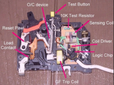
GFCI breakers use two coils.
  1. One coil is used to measure the difference in current between hot and neutral.
  2. The second coil is around neutral and will set up an oscillation if there is a current on the ground. (The only way the oscillation will start is if there is a path between neutral and ground downstream of the GFCI breaker.)
If either the differential coil or the oscillator coil detects a sufficient current for a sufficient amount of time it will open the breaker.

This video has a good explanation of both functions:


Note: I do not know if RCDs that are used elsewhere in the world have the ground current sensing function.
 
Actually, GFCI breaker *do* sense current on the ground circuit.

GFCI breakers use two coils.
  1. One coil is used to measure the difference in current between hot and neutral.
  2. The second coil is around neutral and will set up an oscillation if there is a current on the ground. (The only way the oscillation will start is if there is a path between neutral and ground downstream of the GFCI breaker.)
If either the differential coil or the oscillator coil detects a sufficient current for a sufficient amount of time it will open the breaker.
I would call that a gfci outlet.

I was talking about one of these
Since it doesn't have a ground wire I think it must infer a ground fault from a current mismatch between line and neutral.
I can't find a teardown video though.
 
Last edited:
How much current to cause a significant Ground Fault ?
What is the best way to simulate one (on the PV wires, AC wires, Batteries)? (ie to cause an actual Ground Fault on a Deye Inverter for instance)
And what equipment best suited to detect them?
I want to train people on how to detect ground fault and therefore how to fix it.
"I want to train people on how to detect ground fault and therefore how to fix it."
If you have to ask, you are definately not qualifiued to train anyone. You would probably hurt yourself and others.
 
Actually, GFCI breaker *do* sense current on the ground circuit.

GFCI breakers use two coils.
  1. One coil is used to measure the difference in current between hot and neutral.
  2. The second coil is around neutral and will set up an oscillation if there is a current on the ground. (The only way the oscillation will start is if there is a path between neutral and ground downstream of the GFCI breaker.)
If either the differential coil or the oscillator coil detects a sufficient current for a sufficient amount of time it will open the breaker.

This video has a good explanation of both functions:


Note: I do not know if RCDs that are used elsewhere in the world have the ground current sensing function.
Thank you for posting thie. I learned more. Always a good thing.
 
I would call that a gfci outlet.

I was talking about one of these
Since it doesn't have a ground wire I think it must infer a ground fault from a current mismatch between line and neutral.
I can't find a teardown video though.
Interesting. I had always assumed the breaker has the same two coils.... but it appears they only have the current differential coil.

1665278590413.png
 
Since we are talking about GFCI.... I should probably clarify that I am talking about Class A GFCI. These are specified to trip at 4-6mA.
(Class A breakers are required for residential applications)

There are Class A, B, C, D & E GFCI breakers that have higher trip values and are intended for industrial applications with large machines.
  • Class A: Residential. Up to 240V. 5ma trip
  • Class B: Obsolete
  • Class C: for use in circuits with no conductor more than 300 V to ground (i.e., systems where line-to-line voltage is 480 V or less) where reliable equipment grounding or double insulation is provided.
  • Class D: for use in circuits with one or more conductors more than 300 V to ground (i.e., 600 V systems), and with specially sized, reliable grounding, to provide a low impedance path so that the voltage across the body during a fault does not exceed 150 V.
  • Class E: for systems similar to Class D, but with special high-speed tripping required that eliminates the need for the oversized ground of Class D.
The C, D & E breakers have different trip values but I don't know what they are off-hand. I *think* some of them go up to 30mA.

I know there are different trip values for various RCDs in other parts of the world, but I do not know if there is a similar standard for them.
 
In Europe (and note, whenever I use the phrase "In Europe", I mainly mean Slovakia, but the standards are pretty similar now in the EU), RCDs at the outlet, like US GFCI outlets, are non-existent. Some appliances (like my inflatable hot-tub) have a GFCI on the cord. The RCDs do not monitor the ground conductor. They may or may not be combined with a circuit breaker.

Given that the RCDs here are 30mA, the suggested approach of a test using an LED probably won't work, as common LEDs would use a resistor to limit max current to 20mA.
 
They may or may not be combined with a circuit breaker.
That means its possible to have an un-protected short circuit?
UPDATE: I see you mean the functions can be separated or combined into a single device.
Given that the RCDs here are 30mA, the suggested approach of a test using an LED probably won't work, as common LEDs would use a resistor to limit max current to 20mA.
Do you still have access to incandescent light bulbs?
 
That means its possible to have an un-protected short circuit?
UPDATE: I see you mean the functions can be separated or combined into a single device.

Do you still have access to incandescent light bulbs?
Unprotected short circuit-- well, if someone screws up wiring up the house. ? Hopefully the main breaker will trip in that case before things start smoking!
Incandescent light bulbs? You mean "industrial heat sources"? (I think that's the name used). Last I checked, even 150W ones are available, under that designation!
 
Back
Top