Hey
@Lighthouse Beacon @42OhmsPA or anyone with this inverter or the SNRE original.... Did you have to MODIFY the RS485 com cable from the inverter to the battery? They are telling me I need to modify it for the multiple (rack) batteries to work. I'm really not trusting these guys support given the wifi problems (and lack of support) an now what they are telling me on this.
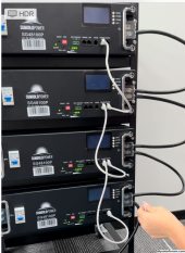
I used the cable that came with the inverter here is what they told me wrt my not seeing multiple batteries:
Dear Customer,
wish you the best day.
Here are steps to build BMS communication between the inverter and battery, please check:
1. Custom-made a BMS cable for the inverter and battery. ( The battery comes with a BMS cable, but you need to make some adjustments to the cable terminal)
For the inverter: pin7 is RS485-A, pin8 is RS485-B,
For the battery

in2 (or7) is RS485-A, pin1(or 8) is RS485-B,.
Please Cut off any excess sequence, pin 7 connects to pin2 (or 7), pin8 connects to pin1(or 8)
If you don't know what that means, you can ask the electrician to help with the BMS cable
2. Connect the pin7+pin8 terminal to inverter RS485 2 port, and connect the other terminal to the battery RS485A port
3. Set battery ADD as attached picture
4. Set the 08 to LFP16, 32 To 485, 33 To PYL. If no 58 code anymore, that means the BMS has been built successfully.
Feel free to contact us if you have any questions.
and then ...
| Kenny Chaffin | | Nov 3, 2023, 8:52 AM (19 hours ago) |
| Are you saying I have to MODIFY the cables that came with my 10K48sp inverter and the cables with each battery? Also, I am not showing an error condition but th |
| | |
Dear Customer,
Happy Weekend.
You can only MODIFY one battery communication cable that is used to conect to the inverter if you need BMS communication.
Once BMS communication is successful, the inverter will show more battery information. But it's okay to use the inverter and batteries without BMS communication.
???