diy solar

diy solar

Install and Operation of the SUNGOLD 10KW 48V SPLIT PHASE SOLAR INVERTER

Ok so LVD - Low Voltage Disconnect .. that doesn't mean anything to a newbie. It could be low AC voltage . Low DC voltage. Low battery voltage...blah blah blah... I appreciate your help but this is why you need to better explain the context. I have no idea what parameter you are referring to.
I should have clarified better on that one.
Screenshot_20240108-204423.jpg
That's what becomes confusing. Clearly you were thinking of a particular parameter or condition but I have no idea what you are saying. Increase your LVD to 48????
Yea, I should have specified which low voltage cutoff. I assumed you'd know I was talking about AC.
Sorry. This stuff is complicated, confusing, and dangerous to boot.
It's only dangerous if you make it ☺
 

Attachments

  • Screenshot_20240108-204423.jpg
    Screenshot_20240108-204423.jpg
    31.7 KB · Views: 4
Was just scouring the manual and focusing in on Params 04 and 05 thinking that is probably what you were referring to.
So the default #04 is 43.6. Why would I want to raise that? To prevent the batteries from dropping that low? Is that damaging to the batteries? Or is would that just for being on the safe side? Also if so why would the default be 43.6 (unless that's for a different type LiPo? battery or Flooded Lead-Acid?) See this is the confusing stuff for us newbies....there are so many possibilities we're trying to comprehend and make sense of. And Gawd Knows SunGold is no help...and the manuals are atrocious.

Thank You!
 
Was just scouring the manual and focusing in on Params 04 and 05 thinking that is probably what you were referring to.
Yes it was, I've been through the manual many times, I've found it covers just about everything after a few times and comprehension.
So the default #04 is 43.6. Why would I want to raise that?
43.6V / 16 = 2.725V / cell. If you look at the charge / discharge curve of LiFePo4 cells you'll it changes quickly at the 'knee'. 2.5V /cell is dead. So that all sounds great, wrong. If you've read the great posts by @Steve_S and many other you'd know the bottom of the working voltage is 3V / cell or 48V for a 16S pack.
To prevent the batteries from dropping that low?
Yes.
Is that damaging to the batteries?
I don't think so short time.
Or is would that just for being on the safe side?
See above, working voltage.
Also if so why would the default be 43.6 (unless that's for a different type LiPo? battery or Flooded Lead-Acid?)
Exactly.
See this is the confusing stuff for us newbies....there are so many possibilities we're trying to comprehend and make sense of.
Understood but you're willing to learn and it will make sense soon enough.
I preach no communications with the BMS and Inverter because it's what I know and have 0 issues with. I can't help as much since I don't use them...
And Gawd Knows SunGold is no help
Nope
...and the manuals are atrocious.
Ehhh, they aren't that bad.
Thank You!
You're welcome.
 
Yes it was, I've been through the manual many times, I've found it covers just about everything after a few times and comprehension.

43.6V / 16 = 2.725V / cell. If you look at the charge / discharge curve of LiFePo4 cells you'll it changes quickly at the 'knee'. 2.5V /cell is dead. So that all sounds great, wrong. If you've read the great posts by @Steve_S and many other you'd know the bottom of the working voltage is 3V / cell or 48V for a 16S pack.

Yes.

I don't think so short time.

See above, working voltage.

Exactly.

Understood but you're willing to learn and it will make sense soon enough.
I preach no communications with the BMS and Inverter because it's what I know and have 0 issues with. I can't help as much since I don't use them...

Nope

Ehhh, they aren't that bad.

You're welcome.
My #4 setting was set by BMS when comms connected:
AD13FA32-A5A7-469D-98BD-30D59A0ACF95.jpeg

Have you been happy with your purchase of the sungold thus far? I, like you, have the Delta Pro and also run the Renogy 550w with great success so far. So far i have 4 renogy 550w panels but the Delta Pro is restricted to 150v and I'm feeling like it's becoming a limitation as my solar array will grow over time. Please let me know how things are going, what you've done and if given the chance anything you would do differently.... thank you!
Yes I have been very happy with the second inverter. I believe my first had an issue when it arrived. I am glad they sent me a new one. I like Sungold 10k (SRNE ASF) It packs a lot of punch for the $1580 spent on it.

$1580 inverter
$1350 batt
$1350 batt

I think it’s a neat setup for $4280 delivered. Is it perfect? Has it been a perfect experience? No. But for $4,280, how much I’m able to run off pure sunlight, and for what I’ve learned along the way.. I say it’s been an awesome product and a fun project
E6545351-9B80-48EC-ACBB-22450B26A2D3.jpeg
 
@Lighthouse Beacon it's weird how your param values were set different than mine...there must be some BMS settings that are set differently that allow/cause that to happen. I'm assuming we have the same BMS - the Pace BMS but that BMS is locked down from what I can tell in each battery. There is a menu item but is says "Manufacturer Only" .. I'm wondering how one might get access to the full BMS?
 
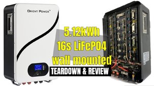
Given the Great GSL Wall Mount Battery FIASCO with LFP cells on their sides & under severe pressure resulting in leaks + worse... I wonder HOW the Cells are arranged inside these wall mounted boxes. Would be great to see photo's with the cover off.
 
Given the Great GSL Wall Mount Battery FIASCO with LFP cells on their sides & under severe pressure resulting in leaks + worse... I wonder HOW the Cells are arranged inside these wall mounted boxes. Would be great to see photo's with the cover off.
I'd vote for that!
 
Yeah I’m almost 100% positive they are laying on their sides, which i had thought about abit prior as not being a great idea… I’ll take a cover off one day I get some time
All literature I’ve read says essentially that any orientation outside of upside down is permissible.
I’m running mine with the studs up (traditional) but they are also in a mobile application. I felt as though they’d be more secure for my situation
There’s at most what, 40lbs of pressure evenly distributed across each bottom cell of each row of 8? Distributed per inch (not doing the math this early) but off the hip doesn’t seem alarming
Yep... I did some reading/research on it as well before deciding to 'mount' my rack mount batteries on their butts on the floor. :)
Should be fine!
 
Wrt my undervolage alarms.. I think maybe I should do some testing ... Load and try to surge the hell out of it and see if I can force it to alarm..switch up bypass.
 
SGP 10kw with two SGP rack batteries. Menu item 12 (Battery Overdischarge voltage). Manually set to 48.0 with the BMS input disconnected. When I connect the BMS it goes to 0. When I reconnect the BMS it stays at 0. The BMS is reporting Discharge Voltage Limit = 43.20 to the inverter but that is not what the inverter is seeing. Ran the same test with my six EG4 batteries. 12 went to 0 with the EG4 BMS connected and did not return to the 48.0 volts I manually set when the BMS is disconnected.

Just fired off an emasil to SGP.

The inverter continuously sends these three commands to the Master battery:
CID2: 0x62 - System Alarm Information: 0x62
CID2: 0x63 - System Charge/Discharge Management Info: 0x63
CID2: 0x61 - System Analog Data: 0x61

This is what I am seeing being sent back to the inverter from the SGP Master battery (keep in mind the batteries are as I received them a week ago, They are in a rack in my computer room and have not been charged since I received them hence the low SOC). The items that end with "Text" are the textual meaning for the number above them and are not sent to the inverter

2024-01-08 21:50:46 TX->:
Valid Packet: True
Version: 20H 32-30
Address: 18 0x12
CID1: 0x46
CID2: 0x62 - System Alarm Information: 0x62
Info Length: 0
Info Data
Command: 7E-32-30-31-32-34-36-36-32-30-30-30-30-46-44-41-39-0D
Sent To Inverter: CID2: 0x62
Description: System Alarm Information
Alarm 1 Value: 0
Alarm 2 Value: 0
Protection 1 Value: 0
Protection 2 Value: 0
Alarm 1 Text:
Alarm 2 Text:
Protection 1 Text:
Protection 2 Text:
2024-01-08 21:50:47 TX->:
Valid Packet: True
Version: 20H 32-30
Address: 18 0x12
CID1: 0x46
CID2: 0x63 - System Charge/Discharge Management Info: 0x63
Info Length: 0
Info Data
Command: 7E-32-30-31-32-34-36-36-33-30-30-30-30-46-44-41-38-0D
Sent To Inverter: CID2: 0x63
Description: System Charge- DischargeManagement Info
Charge Voltage Limit: 56.40
Discharge Voltage Limit: 43.20
Charge Current Limit: 100.00
Discharge Current Limit: 200.00
Charge/Discharge Status (bit flags for below values): 192
Charge Enable Value: 0
Charge Enable Text: Normal
Discharge Enable Value: 0
Discharge Enable Text: Normal
Charge Immediately: 0
Charge Immediately Text: Normal
Full Charge Request: 0
Full Charge Text: Normal
2024-01-08 21:50:47 TX->:
Valid Packet: True
Version: 20H 32-30
Address: 18 0x12
CID1: 0x46
CID2: 0x61 - System Analog Data: 0x61
Info Length: 0
Info Data
Command: 7E-32-30-31-32-34-36-36-31-30-30-30-30-46-44-41-41-0D
Sent To Inverter: CID2: 0x61
Description: System Analog Data
Average Battery Voltage: 52.57
Total Current: 0.00
Average SOC: 43.00
Average Cycles: 1.00
Maximum Cycles: 1.00
Average SOH: 100.00
Minimumn SOH: 100.00
Max Cell Voltage: 3.29
Battery # Of Max Cell Voltage: 16
Min Cell Voltage: 3.29
Battery # Of Min Cell Voltage: 32
Average Cell Temp: 84.88
Max Cell Temp: 84.99
Battery # Of Max Temp: 6
Min Cell Temp: 84.83
Battery # Of Min Temp: 4
Average MOSFET Temp: 85.32
Max MOSFET Temp: 85.35
Battery Number Of Max MOSFET Temp: 2
Min MOSFET Temp: 85.28
Battery Number Of Min MOSFET Temp: 1
Average BMS Temp: 85.21
Max BMS Temp: 85.32
Battery Number Of Max BMS Temp: 2
Min BMS Temp: 85.10
Battery Number Of Min BMS Temp: 1

Note the "Pack UV Alarm(V)" setting of 43.20 which is what is being sent to the inverter (supposedly)
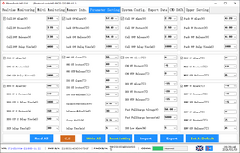
BMS_Parameter_Settings.png
 
For me it's been Alisa and she has been pretty good at responding to my emails, often times with a bit of a delay.

Give your setup a try. Maullay set 12 with the batteries disconnected. Then connect the BMS and see it it goes to 0.
 
I just kinda slammed my system with the higher powered things I have on it while at about 70% SOC....hit almost 3kw and battery dropped to 50.3 but did not alarm.
 
For me it's been Alisa and she has been pretty good at responding to my emails, often times with a bit of a delay.

Give your setup a try. Maullay set 12 with the batteries disconnected. Then connect the BMS and see it it goes to 0.
Yeah, I've been threatening to do a Factory Reset on the Inverter and check the default values before connecting batteries and then do a comparison. Have not stooped to trying that yet.
 
The other thing you can do when the inverter is putting out say 8kw and it's pull over 100 amps from the battery is to measure voltage drop between the battery cable inverter connection and the battery. With my inverter loaded (HVAC running, hot watter heater kicked on and a load in the dryer, plus lights, tv and several computers) My Klien clamp on amp meter and Victron shunt show around 175 amps being pulled from the batteries. I measured a 0.3 volt drop from the battery rack positive bus bar and the positive connection on the inverter (I suspect this is because of the 200 amp breaker). The negative side, almost no drop. In addition I measured across the cable from each battery to the bus bar and saw no voltage drop. Measured current from each battery to the bus bar and they were all very close.

If your batteries are still connected as a previous picture showed, each battery in parallel using the SGP supplied cables, and without "stacking" lugs you have to have the positive connected to an end battery (negative to the other end battery?). If the whole battery stack has to provide 120 amps to the inverter then each battery (I assume you still have 5), should contribute 24 amps. The cable from the end battery to the next would then have to carry the current from the other four batteries or 96 amps, the cables provided with the batteries are not rated for that kind of current, hence the need for bus bars.
 
I don't get it.

Closed loop causes issues. I don't see an advantage to having coms vs not having coms.

Use a smart shunt to know how much power is actually in the batteries and set the inverter to do what it should do and enjoy the system.

Anything after 1 battery is going to make the coms setup a pain anyways I would think with the weakest link battery wise dictating if you can power your home or not.

Use the bms's in the battery to determine if a battery has an issue and not if your house lights work or not to determine if you have a single battery causing problems.....

Just seems a far simpler way to live.
 
The other thing you can do when the inverter is putting out say 8kw and it's pull over 100 amps from the battery is to measure voltage drop between the battery cable inverter connection and the battery. With my inverter loaded (HVAC running, hot watter heater kicked on and a load in the dryer, plus lights, tv and several computers) My Klien clamp on amp meter and Victron shunt show around 175 amps being pulled from the batteries. I measured a 0.3 volt drop from the battery rack positive bus bar and the positive connection on the inverter (I suspect this is because of the 200 amp breaker). The negative side, almost no drop. In addition I measured across the cable from each battery to the bus bar and saw no voltage drop. Measured current from each battery to the bus bar and they were all very close.

If your batteries are still connected as a previous picture showed, each battery in parallel using the SGP supplied cables, and without "stacking" lugs you have to have the positive connected to an end battery (negative to the other end battery?). If the whole battery stack has to provide 120 amps to the inverter then each battery (I assume you still have 5), should contribute 24 amps. The cable from the end battery to the next would then have to carry the current from the other four batteries or 96 amps, the cables provided with the batteries are not rated for that kind of current, hence the need for bus bars.
This makes sense
 
@Crowz and @42OhmsPA yes... sure seems that way.... it's like the inverter and BMS's are fighting for control and there's no Supreme Court to appeal to.
I feel like my BMS is setting more reasonable values. That low voltage param seems too low for your system? I am trying not to range my batts to hard early in lifecycle
 
All literature I’ve read says essentially that any orientation outside of upside down is permissible.
I’m running mine with the studs up (traditional) but they are also in a mobile application. I felt as though they’d be more secure for my situation
There’s at most what, 40lbs of pressure evenly distributed across each bottom cell of each row of 8? Distributed per inch (not doing the math this early) but off the hip doesn’t seem alarming
Yes it should be fine regardless I think. Likely leaks occur from under volt and over volt aggressive cycling. Cylindricals don’t mind I assume, since you see them on sides in Tesla Powerwalls etc. these prismatic and “eve” style batts would prob be safer caps up to prevent gassing pushing out liquid electrolyte, but I mean in the grand scheme I think it’s pretty null for me in my system. I didn’t want a floor footprint in my garage and this is a tiny system with low price point. I’m not afraid to replace the entire thing in 3-5 years
 
I don't get it.

Closed loop causes issues. I don't see an advantage to having coms vs not having coms.

Use a smart shunt to know how much power is actually in the batteries and set the inverter to do what it should do and enjoy the system.

Anything after 1 battery is going to make the coms setup a pain anyways I would think with the weakest link battery wise dictating if you can power your home or not.

Use the bms's in the battery to determine if a battery has an issue and not if your house lights work or not to determine if you have a single battery causing problems.....

Just seems a far simpler way to live.
I’m just letting mine run. Like you said. I just ignore it and it’s been working better since I quit messing with everything, lol
 
Yes it should be fine regardless I think. Likely leaks occur from under volt and over volt aggressive cycling. Cylindricals don’t mind I assume, since you see them on sides in Tesla Powerwalls etc. these prismatic and “eve” style batts would prob be safer caps up to prevent gassing pushing out liquid electrolyte, but I mean in the grand scheme I think it’s pretty null for me in my system. I didn’t want a floor footprint in my garage and this is a tiny system with low price point. I’m not afraid to replace the entire thing in 3-5 years
Yep. Even though it's a big outlay for me...the inverter itself was low priced and the batteries and panels can be reused!
I have no issue with replacing the inverter or individual batteries as needed.
 

diy solar

diy solar
Back
Top