diy solar

diy solar

Install and Operation of the SUNGOLD 10KW 48V SPLIT PHASE SOLAR INVERTER

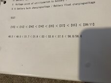
I did it. I factory default reset the invert (got an email telling me to do it). Attached is a spreadsheet where I collected the data under various inverter conditions. Each column shows the values I recorded under each condition. It was interesting to note that the BMS only affected menu items 9 and 11. They are set by the BMS when connected and revert back to the manually set (or default) values if the BMS is disconnected. In addition a number of the menu items are interrelated, changing one will change another or the range you can set will be limited by what is set in another menu item. 【15】<【12】<【04】<【14】<【35】<【37】<【05】<【09/11】this means each item to the left must be of a lesser value and in most cases you cannot set a menu item to less than the item to it's left or higher than the item to it's right (or the item being changed will change the item to it's left or right to comply with the rule). When I connect the BMS and item 12 goes to zero, it violates the rule of being greater than item 15 and that item 15 should be less then item 12. It is also interesting to note that if I turn off the inverter, disconnect the BMS, and turn the inverter back on item 12 is restored. When I reconnect the BMS item 12 goes to zero.

I will send these findings to SGP and see what they have to say. I do not like the idea of 12 going to zero since it a setting that affects whether/when the inverter shuts off the AC output
 

Attachments

  • SungoldPower_10kw_Inverter.zip
    9.2 KB · Views: 13
Alisa seems to respond much faster than Cindy:
My email:
My concern is that menu item 12 does not return to the manually set value if the inverter loses communications with the batteries as do several other battery related settings.

If I manually set menu item 9 for example to something significantly different than what the BMS reports. I can see this value revert to the manual setting if I disconnect the BMS and revert to the BMS setting once I reconnect the BMS.

In addition, menu item 12 will turn off inverter output whereas (according to the manual) menu item 58 is just an alarm setting and does not turn off inverter output.

Since the inverter cannot determine battery state of charge but can only really monitor battery voltage it makes more sense for the inverter to respond to battery voltage issues rather than state of charge.

SGP response:
If you don't build BMS between the inverter and battery, you can try to set the inverter back to default status, here is the step:
Only connect the inverter to the battery, and press the inverter (up and down) button simultaneously for more than 3 seconds, the inverter will make a beeping sound or a white frame will appear. Then turn off the inverter and restart it.
Please kindly note that the setting of parameters should follow the following principles
【15】<【12】<【04】<【14】<【35】<【37】<【05】<【09/11】

I will have to look up each of these settings to see if the answer makes sense. Time to quite so I can go enjoy some 18 year old scotch.

That makes sense for me:

Battery undervoltagelimit voltag < Battery overdischargevoltage (delay off < Voltage point of batteryswitch to utility < Battery undervoltagealarm < Battery under voltagerecover point < Battery full rechargevoltage point < Voltage point of utilityswitch to battery < Battery bulk chargingvoltage / Battery float chargingvoltage

【15】<【12】<【04】<【14】<【35】<【37】<【05】<【09/11】

46.5 < 48.8 < 49.2 < 49.6 < 52.8 < 53.6 < 57.6 < 56.8/56.8
 
Last edited:
I did it. I factory default reset the invert (got an email telling me to do it). Attached is a spreadsheet where I collected the data under various inverter conditions. Each column shows the values I recorded under each condition. It was interesting to note that the BMS only affected menu items 9 and 11. They are set by the BMS when connected and revert back to the manually set (or default) values if the BMS is disconnected. In addition a number of the menu items are interrelated, changing one will change another or the range you can set will be limited by what is set in another menu item. 【15】<【12】<【04】<【14】<【35】<【37】<【05】<【09/11】this means each item to the left must be of a lesser value and in most cases you cannot set a menu item to less than the item to it's left or higher than the item to it's right (or the item being changed will change the item to it's left or right to comply with the rule). When I connect the BMS and item 12 goes to zero, it violates the rule of being greater than item 15 and that item 15 should be less then item 12. It is also interesting to note that if I turn off the inverter, disconnect the BMS, and turn the inverter back on item 12 is restored. When I reconnect the BMS item 12 goes to zero.

I will send these findings to SGP and see what they have to say. I do not like the idea of 12 going to zero since it a setting that affects whether/when the inverter shuts off the AC output
great work that makes logical sense, good looking spreadsheet. your findings are definitely a bug. A++
 
Last edited:
Not sure if this will work or not...my colors are definitely not coming through. :(

I stole your spreadsheet and edited my values in...

see attached pdf...


Attachments

  • MySGP10k48InverterSettings.pdf
    194.6 KB · Views: 7
Last edited:
I did it. I factory default reset the invert (got an email telling me to do it). Attached is a spreadsheet where I collected the data under various inverter conditions. Each column shows the values I recorded under each condition. It was interesting to note that the BMS only affected menu items 9 and 11. They are set by the BMS when connected and revert back to the manually set (or default) values if the BMS is disconnected. In addition a number of the menu items are interrelated, changing one will change another or the range you can set will be limited by what is set in another menu item. 【15】<【12】<【04】<【14】<【35】<【37】<【05】<【09/11】this means each item to the left must be of a lesser value and in most cases you cannot set a menu item to less than the item to it's left or higher than the item to it's right (or the item being changed will change the item to it's left or right to comply with the rule). When I connect the BMS and item 12 goes to zero, it violates the rule of being greater than item 15 and that item 15 should be less then item 12. It is also interesting to note that if I turn off the inverter, disconnect the BMS, and turn the inverter back on item 12 is restored. When I reconnect the BMS item 12 goes to zero.

I will send these findings to SGP and see what they have to say. I do not like the idea of 12 going to zero since it a setting that affects whether/when the inverter shuts off the AC output
Thanks for this! The relationship between the items/params is interesting ... will have to study it more to better understand.

Downloaded the zip but it will not let me extract file/s.
 
Thanks for this! The relationship between the items/params is interesting ... will have to study it more to better understand.

Downloaded the zip but it will not let me extract file/s.
I attempted to enter these values to see if my #59 discharging SOC would automatically change, since it won’t let me change #59 or #61. I don’t want to run the batts under 20% SOC.

It rejected my changes and did not save them. I was hoping it would since it reads “parameter can be set only when battery type is USER and L16” which I am L16; but I guess BMS is priority over inverter param defined ?
E8F3C2F7-3DAA-4559-8883-C27AC87672C7.jpeg
 
I attempted to enter these values to see if my #59 discharging SOC would automatically change, since it won’t let me change #59 or #61. I don’t want to run the batts under 20% SOC.

It rejected my changes and did not save them. I was hoping it would since it reads “parameter can be set only when battery type is USER and L16” which I am L16; but I guess BMS is priority over inverter param defined ?
View attachment 188306
Interesting. So you can't actually do that manually unless you are in "User" battery mode right?

Were you able to read @marionw 's zip/file? It won't extract here after I download. under Windows 11...
 
Interesting. So you can't actually do that manually unless you are in "User" battery mode right?

Were you able to read @marionw 's zip/file? It won't extract here after I download. under Windows 11...
Yeah it worked for me, excel spreadsheet. I don’t think I have to be in user mode I think I gotta switch BMS comms off change #32 to SLA

Does it let you change any of those values?
 
My SGP10k48 inverter is connected to an EG4 Communications Hub which is connected to 6 EG4 Lifepower4 batteries in a 6 battery rack with bus bar.
I needed the Hub as the EG4 batteries use a Narada BMS which would not talk to the Inverter using the Pylontech protocol. The hud does the translation.
The EG4 batteries only have 2 RS485 ports similar to the two on the right of the SGP batteries (The parallel port) but EG4 uses them is a slightly different manner. EG4 only talks one protocol where the SGP uses PACE on the parallel and the RS232 ports and Pylontech on RS485A/CAN which is why the inverter connects via the CAN or RS485A. With the EG4's SA connects to an RS485 on pins 1&2. With the SGP it connects via the RS232 on the master battery(the one with address 1).

I connected the SGP master battery to the invert (top one set to address 1) and it had the same symptoms with respect to menu item 12 as the EG4 Hub/batteries so it is not a battery BMS issue.

The voltages in the spreadsheet where recorded using the EG4 batteries. I nend to connect the SGP batteries to the inverter to see if menu items 9 and 10 are different
 
OMG Kenny you are still fighting that bad battery
Yes and no.... Battery #5 is still a bastard. It's pulling down the total average system voltage/etc I believe.

I think the next step is to get everything up to full charge. Disable #5 and see what happens next.

I could go to User mode but think I'll try without #5 for a bit while we are having snow, clouds etc and see what happens...
 
So if the errant battery cannot sustain a heavy load and craps out, it could take the whole rack down just long enough to fault the inverter.
Try removing it from the comms and let it piggy back.
 
So last night as the batteries were approaching the bottom I found out how I could connect the PBMS software to both the master battery i.e. #1 as well as individually to each of the other batteries using the USB -> RS232/Rj11 console connection. I can look at all/each of the batteries/packs if I plug in to the master battery and select the appropriate pack.

I can also plug the rj11 into each of the other battery's console jack and view the information.

I tried it using the RS485A port(s) an couldn't get it to connect...maybe because of the type of usb -> RS485 cable?

Has anyone been able to connect the PBMS Software on a pc to the batteries via a USB -> RS485 cable?

Should I ask Cindy? :)
 
So if the errant battery cannot sustain a heavy load and craps out, it could take the whole rack down just long enough to fault the inverter.
Try removing it from the comms and let it piggy back.
Yep, my thought as well but I was not considering the "Piggy-Back" strategy....I was going to turn it off and disconnect the comm cable, but just removing the comm cable could work too and perhaps provide additional information. I'm not certain that the BMS is sending anything that is causing this... I think it is the inverter itself detecting the battery voltage dropping below 49 V but I think it may be battery #5 that is pulling it down so leaving it 'piggy back' might not change anything. Would be interesting to know though!

I spoke/wrote of this before but it just annoys the hell outta me that a single bad cell can 'take down' the whole system. That's just bad design!/Bad System Design!
 
It's all about the bad cell I think.
The #5 BMS says "oh shit", the inverter says "why" then "crap a battery error, let me panic about that"
No comms to that battery pack might = no error and panic.
Is it right you have to do this, NO.
Get Sungold to replace the battery....you would be the first successful person in the world to persuade "Cindy" to give meaningful customer service.
 
With the PbmsTools (or SOKTool) tool, before you click the "Open" button for the serial port select "FF" in the "Pack" dropdown. Open the serial port and now you can click on each battery icon to view that battery. If you use the SOKTool software and enter "paceadmin" for the password you will have access to several other tabs on the main window. Select the "Multi Monitoring" tab, check the "Save to database" checkbox and the grid will start to fill with data from all the batteries, you can then click the "Export" button and save the data for all batteries to a spreadsheet. Now you can compare the batteries including individual cell voltages. You can download the SOKTools from the Current Connected website.

The Pbmstools with connect on the RS485B or RS485C ports as long as no battery address is set to 1 or battery 1 is not connected to either of these ports (battery 1 is communicating with the other batteries and this creates a communication conflict with the tool) The Pbmstools software talks the "PACE" protocol and the RS485A port talks the "Pylontech".

With your computer connected to the RS232 jack on the battery with address 1, just select "FF" for the "Pack" before opening the serial port.
 

diy solar

diy solar
Back
Top