Fronius inverters for sure, had a direct communication with their engineers. Most companies don't even know what I'm talking about. Attached document details the problem but you may not be able to follow unless your an inverter design engineer.
"The closest approach possible
has been demonstrated by the attachment of a thermistor to the center, or drain lead of a MOSFET package
such as a TO3-PI as shown in Fig. 9"
Guilty as charged.
Wasn't a switch-mode MOSFET inverter application, rather a linear bipolar RF amplifier. But I put a PTC thermistor there as part of bias current temperature compensation.
That whole MOSFET "SOA" isn't safe thing occurs when MOSFET is used as a linear component, not switching.
Playing with gate voltage to balance currents I would think would still be very low Vds, but would cause more heating.
"The solution is simple. A transformerless inverter should have a mechanical relay or contactor in its output
circuit, normally open. A “dc detector” should then drive this relay such that the relay is enabled only when no
dc is detected on the inverter output. This could certainly be a defining feature for high-end transformerless
inverters. Obviously transformer-output inverters are immune to this problem"
Ahh, there it is. And here I thought you were asking me to find the protection in a schematic.
No, I'm not an inverter design engineer. But I have dug through the innards of some systems, and designed a few small things.
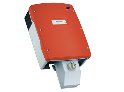
The SMA inverters do have relays. The first transformerless models had very loud relays, bigger than usual and with strong springs, I would say. Installation was also required to have fuses on both PV+ and PV-.