Sorry to bring up an old thread but I have been attempting to get some clarification on this question.
I am using 2x
SP6548 in split phase to get to 240v. I will use the Units and Panels as the primary source of power during the day but have the grid available for recharging the system if the panels are not performing well enough to do so by themselves
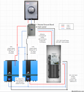
The proposed wiring will look like this -
I have an emergency disconnect directly after the meter.
It will service ac input power to the units and can continue doing so after i turn the main off at the sub panel which services the house.
the sub panel has a interlock kit on it that will let me switch between the grid input and a 60amp input that the ac output from the inverters will send power to.
View attachment 176706
The Neutral Ground bond is acheived at the main \ emergency disconnect panel
So i was not sure if i would need to remove the bonding screw from the units.
So after reading this thread i reached out to support from sungoldpower and i am just not sure if i trust their response 100%
so originally i provided them the drawing above and asked if i needed to remove the screw - they responded with
View attachment 176708
So i replied asking - What scenerio would involve me removing that screw - they responded with
View attachment 176709
So they advised you would NEVER remove the screw - which doesnt seem accurate.
any input on the proposed setup would be great - thanks!