diy solar

diy solar

Neutral ground bond totally off grid w generator and reliable inverter

SeanWatts

New Member
Joined
Jun 29, 2021
Messages
50
I am wiring up a breaker box for an off grid cabin. No grid power of any sort on the property at all.

Do I bond neutral and ground in the breaker box? The ground will be wired to an 8' copper rod outside. I read some other posts and they said adding a generator complicates things, weather the generator also bonds ground and neutral or not. Also weather the inverter bonds neutral and ground or not. There will be a transfer switch to change from solar to generator power.

I watched a video where the reliable inverter popped the internal fuses because the neutral and ground where bonded.

How do I check to see if the generator, and or the inverter are bonded?

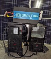
The generator is a predator 4550 inverter style, and the dc to ac inverter is a 3000 watt 24v reliable.
 
Last edited:
Generators have floating grounds.

There must only be ONE N-G bond in the system. Either at the panel, or at the Inverter. Inverter behavior also matters. If the inverter has the N-G bond, but it breaks the N-G bond when receiving AC input, then you need it at the panel since the generator doesn't have an N-G bond and disable the N-G bond at the inverter when inverting.

I have a 3850 predator. I also have a 24V 2000W Reliable as backup to my Quattros, but I can't remember how it handles N-G.
 
Is there any way to verify if your system has only one Neutral-Ground bond?

Edit: besides manually opening everything and checking which may not be easy to do with an inverter for instance.
 
I have a 2500W 48V WZRELB where I backfeed my house breaker panel by terminating all three leads, effectively bonding the inverter neutral and grounding the case. No changes to the inverter internal wiring. Without bonding I measure a floating 60V hot-ground and 60V neutral-ground.

As an initial test I temporarily connected a neutral inline 5A fuse in the event of a 60V short. Worked just fine, no smoke and did not blow the 5A fuse after loading to around 4.5A. Since then I have pushed the WZRELB hard multiple times, especially during the great Houston freeze where it ran my furnace to keep the pipes from bursting. No problems so far with the grounding or GFCI outlets.

However I always connect the inverter to the breaker panel first before powering it on.
 

Attachments

  • UPS Reliable.jpg
    UPS Reliable.jpg
    211.6 KB · Views: 20
Last edited:
With the generator disconnected, and off...
Check continuity between N and G...
With the generator off and disconnected, I tested continuity at the 30a plug, which is what I would be using. With the black wire from multi meter in the ground, I get continuity on both hot and neutral. Does that sound right?
 
With the generator off and disconnected, I tested continuity at the 30a plug, which is what I would be using. With the black wire from multi meter in the ground, I get continuity on both hot and neutral. Does that sound right?
More details on what you are testing.
Hot shouldn't be in the testing for a N-G bonding test.
 
You should bond and ground in the panel, and your inverter and generator should be unbonded.

The only reason to go otherwise, is if you're limited by bad inverter design. If you haven't bought an inverter yet then good, bond the panel and don't buy a bad inverter.
 
More details on what you are testing.
Hot shouldn't be in the testing for a N-G bonding test.
What other details would you like? When doing the continuity test on the generator 30a plug, I did not know which was hot and which was neutral, so I put the black probe in ground, then put the red probe in both of the other spots, and got continuity on both.


It makes sense that I did not need to test hot, I just didn't know which was hot or neutral.


So, since I am getting continuity going from ground to hot, and ground to neutral, I know that neutral and ground are bonded in the generator, right?
 
With the generator off and disconnected, I tested continuity at the 30a plug, which is what I would be using. With the black wire from multi meter in the ground, I get continuity on both hot and neutral. Does that sound right?
N/G bond exists.
 
You should bond and ground in the panel, and your inverter and generator should be unbonded.

The only reason to go otherwise, is if you're limited by bad inverter design. If you haven't bought an inverter yet then good, bond the panel and don't buy a bad inverter.
With my set up it’s not so simple. My cabin panel is unbonded. I have a victron multiplus being fed AC input from a pheonix inverter 90% of the time. I also use two generators one 3400w with a floating neutral and a smaller 1800w inverter generator that is bonded. I had to leave my cabin panel unbonded for when I use the smaller generator. I use a neutral/ground bonding plug on the larger generator and also bonded the pheonix inverter. The multiplus switches the N/G bond automatically. Both gen sets and pheonix plug into the multiplus AC IN depending on my needs for power
 
You should bond and ground in the panel, and your inverter and generator should be unbonded.

The only reason to go otherwise, is if you're limited by bad inverter design. If you haven't bought an inverter yet then good, bond the panel and don't buy a bad inverter.
No… the N-G bond should be in the first disconnect from power.
Either in the transfer switch, if you have one, or if there is an interlock, the N-G bond should be there…
 
With my set up it’s not so simple. My cabin panel is unbonded. I have a victron multiplus being fed AC input from a pheonix inverter 90% of the time. I also use two generators one 3400w with a floating neutral and a smaller 1800w inverter generator that is bonded. I had to leave my cabin panel unbonded for when I use the smaller generator. I use a neutral/ground bonding plug on the larger generator and also bonded the pheonix inverter. The multiplus switches the N/G bond automatically. Both gen sets and pheonix plug into the multiplus AC IN depending on my needs for power
It would be that simple if you didn't use the bad generator.
Either in the transfer switch, if you have one, or if there is an interlock, the N-G bond should be there…
Not familiar with transfer switches and if those are a typical bonding point. Interlock as I'm familiar with would be an interlock in the panel so that sounds like what I said.
 
I have made some progress towards my cabin build for earth ground with this inverter brand. I have two of them and they both came wired incorrectly. I’ve made some videos explaining and testing the cross wiring of the 120v outlets. If you own a WZRELB reliable inverter you should check out these videos. It’s easy to test to see if you have a polarity problem. The fix is a 5 minute job.
 
Last edited:
I have made some progress towards my cabin build for earth ground with this inverter brand. I have two of them and they both came wired incorrectly. I’ve made some videos explaining and testing the cross wiring of the 120v outlets. If you own a WZRELB reliable inverter you should check out these videos. It’s easy to test to see if you have a polarity problem. The fix is a 5 minute job.
Just removing the ground from the circuit board. Will give you the same results. Without switching the red and black wires. The 60v reading is just measuring the potential. (Between a live circuit and an un bonded conductor) potential is usually around 1/2 the circuit voltage. Which is what you would also read at your panel. If you hadn't created a N/G bond with the white wire across the top of the panel.
Incidentally, your N/G bond (in the panel) is also backfeeding into the inverter and providing N/G bonding for the inverter mounted receptacles.
Removing the ground will not reverse the outlet polarity which is what switching the wires does. The outlet is not wired correctly. It should not be UL listed, if the neutral outlet is “hot”.
The ground disconnect to the circuit board was to disprove the theory that it is was using the ground as a return line for the 60v 60v split phase design theory.
 
The ground disconnect to the circuit board was to disprove the theory that it is was using the ground as a return line for the 60v 60v split phase design theory.
Did you replace the ground connection, afterwards?
If so, then you should keep the black and red switched. Because of the board arrangement. In combination with adding a N/G bond.
 
Last edited:
Back
Top