You are using an out of date browser. It may not display this or other websites correctly.
You should upgrade or use an alternative browser.
You should upgrade or use an alternative browser.
New Supplier for 280Ah cells: Shenzen Basen
- Thread starter Haugen
- Start date
My EPEver Tracer manual says 5amp per mm2I'd be also curious to have some expert's opinion on this. The only rule of thumb I found is 1.4 x area in mm2 for copper. That would make 56Ah for a 40mm2 section ?
I would be very hesitant to put that kind of current through this small of a bus bar. I don't doubt that it will handle it, but there will definitely be a temperature rise."Copper Busbar Rating - Austral Wright Metals -" https://www.australwright.com.au/technical-data/advice/copper-busbar-rating/
Everything I have read indicates 1.6A per mm^2 of copper and 1.0A for aluminum.
If your bus bars are out in the open with nothing combustible anywhere near, you are probably fine. I wouldn't put it in an RV or my house.
Yea...I'll perhaps take time tommorow to get the formula to calculate all this. We also got to keep in mind that it's very short and length is an important factor. In fact you can put lot of amp in a wire...it will just heat, then finally burn if it can't dissipate ....a lot of energy could be lost in this heating....That doesn't sound right to me.
I'm not well versed in calculating Busbar Ampacity but:
The dimensions shown are 2mm x 20mm (40 mm²)
I can't find a good metric ampacity table so this one will have to do
The smallest busbar on that list 1/8" x 1/2" is also roughly 40 mm²
and is rated for only 150A DC
For reference 40 mm² = 79,000 circular mils = a cross section in between 2AWG and 1AWG
Maybe someone with more knowledge than me clarify, but based on the above I would not trust those busbars to carry anywhere near that much current safely.
What I want to say (sorry I'm french and my English is not mature enough to explain all my though) is that those busbar can certainly take 400A...the question is .....how much time...?
I believe we are talking about battery busbars here, so they will definitely not be in open air with nothing of consequence around.If your bus bars are out in the open with nothing combustible anywhere near, you are probably fine. I wouldn't put it in an RV or my house.
I'd be also curious to have some expert's opinion on this. The only rule of thumb I found is 1.4 x area in mm2 for copper. That would make 56Ah for a 40mm2 section ?
I saw that too, and the first calculator I used returned the same number, but then I recall seeing somewhere that that rule of thumb only applied over some number of amps or some size of busbar.
Adding to the uncertainty. most calculators (probably all calculators) for busbar ampacity seem premised on distribution type busbars, not battery cell connections. At the end of the day a hunk of copper is a hunk of copper, but looking at some of these busbar ampacity charts they list 30*, 60*, or 90* rise in temperature, I suspect even the lowest figure is more than one would want on the battery terminals. If ambient is 30*C and you increase the temperature 30*C over ambient that is 60*C at the terminals (which is ~175 Fahrenheit). I'm not informed enough to know this is bad, but I'm also not informed enough to know its not bad, and reflexively it sure don't feel good, particularly considering that heat is the primary cause of the early death of lifepo4 cells.
Keith C
Ahhh, the sharks have him.


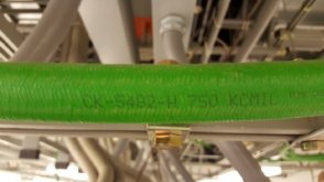
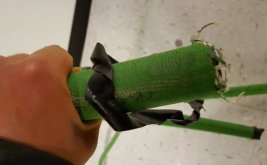
Busbar... How about just use cable.. This green stuff was only the ground cables at a place I was helping re-commission. We pulled out all the DC cable and scrapped it. $64,000 of scrap. !!! I was shocked.
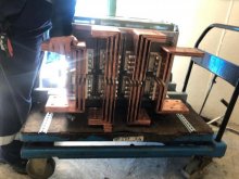
The busbar was 12 inches wide and 3/8" thick and it was ALL doubled-up to be 3/4" thick. The batteries where each 4 feet wide and 8 feet long and filled a room the size of a basket ball court.
The battery chargers... nine of them. 800A @ 58V

Last edited:
So how much current was going through those bus bars? If those measurements are accurate, please give us a figure of Amps per mm^2 cross section and what temperature rise was experienced.View attachment 27014
View attachment 27015
Busbar... How about just use cable.. This green stuff was only the ground cables at a place I was helping re-commission. We pulled out all the DC cable and scrapped it. $64,000 of scrap. !!! I was shocked.
The busbar was 12 inches wide and 3/8" thick and it was ALL doubled-up to be 3/4" thick. The batteries where each 4 feet wide and 8 feet long and filled a room the size of a basket ball court.
The battery chargers... nine of them. 800A @ 58V
View attachment 27018
Keith C
Ahhh, the sharks have him.
Sorry but it's unclear to me how to arrive at those numbers because the busbars had the battery chargers running to them at various locations and then the loads were pulled off in a distributed manner all over the busbars and routed to a dozen DC distribution panels. It wasn't a simple clean 'batteries here load there' type system. It was a massive phone switching system facility (World Com).
Are you asking about short circuit aspects?
Or a steady-state operating thermal limit?
Do you have a voltage drop you're willing to live with at a maximum normal discharge rate?
What exactly are you seeking?
Are you asking about short circuit aspects?
Or a steady-state operating thermal limit?
Do you have a voltage drop you're willing to live with at a maximum normal discharge rate?
What exactly are you seeking?
The conversation has recently turned to the current capacity of bus bars by the area of the cross section. It sounds like you have expertise in the subject.Sorry but it's unclear to me how to arrive at those numbers because the busbars had the battery chargers running to them at various locations and then the loads were pulled off in a distributed manner all over the busbars and routed to a dozen DC distribution panels. It wasn't a simple clean 'batteries here load there' type system. It was a massive phone switching system facility (World Com).
Are you asking about short circuit aspects?
Or a steady-state operating thermal limit?
Do you have a voltage drop you're willing to live with at a maximum normal discharge rate?
What exactly are you seeking?
I'm hoping you can provide information whether technical sources, or anecdotal from experience to put to rest the debate over how much current you can safely pass through a bus bar.
Lots of math, but pretty straight forward. There is some iteration it seems to come up with a bus bar which meets your max temperature rise. Note that the shape of the bar and how much cooling it gets plays a significant role.
Keith C
Ahhh, the sharks have him.
Luthj's find is the whole shebang rolled into one document. Nice find! The salient points are this.
1) Any heat is from power loss (waste) and in our typical solar systems should be avoided as much as possible.
2) Heating busbar means it's changing size.
3) Mechanical stresses cyclically occurring are bad for batteries and connections if the busbars are directly attached to battery posts.
4) Directly connected to batteries busbars should not probably cycle more than 10C (~20F)
5) Any losses in busbars represents lost voltage potential that greatly impacts system performance in the low voltage systems we're generally working with in DIY power systems. The voltage losses cause inverters to shutdown prematurely. If the loss is great enough it can cause damaging system instabilities. Galloping, where the inverter shuts down due to low input voltage that then causes an immediate voltage bounce once the load has been dropped causing the inverter to restart only to have the load drop the voltage below the cutoff - around and around until the pass-elements in the inverter let go.
6) As can be seen by Luthj's document there is a lot to consider in fully specifying an optimum busbar.
Notably the:
a) shape
b) orientation
c) ambient air temperature
d) air velocity
e) current
f) mounting method
g) frequency of the current (ignorable if DC)
On small systems like ours where we really don't want any voltage drops at all it's generally just simpler and more sure-fire to over spec the busbars. The price difference when not measured in 10's of pounds of copper renders detailed calculations based on specific, but in our case, often hard to define details, makes working the numbers non-feasible.
When I do small systems I look at what's usually used in a particular power level design and go with that. Then during commissioning I actually gun the bars and all connections looking for anything too warm. >10C over ambient. If there is something exceeding that temperature I consider doing something about it. If it rises to, say, 14C I consider, 'will this setup actually be running at the maximum limit or is it expected to really only run at something less', (normally the case). If the maximum load is only for starting motors or brief heating tasks I'll do nothing. Otherwise I'll add more copper. If say the supplied busbars that came with the batteries is allowing too high a temp-rise in the particular application I'll either acquire another entire set and double them up (very effective) or I'll pitch them and go the classic copper pipe method since often flattened copper pipe is thicker cross-section than provided busbars and it's pretty easy to work with and certainly inexpensive.
An easy, though usually over sized method, for determining minimum bus bar size.
-Consult the 90C insulation ampacity table for standard cable (AWG or metric) for your expected max continuous current.
-Convert the AWG to cross sectional area.
Take the cross sectional area, and find an equivalent bus bar. Its typically okay do go down 1AWG size, as bus bars will be rectangular usually, and thus have more surface area than a cable.
Roughly in a system like mine... 5kw inverter, 13kwh Eve, I can't durably accept more then 2% loss in my busbars ( I meant total over 15 bars), at full power it would mean 100w/15, that's 7 watts to dissipate per busbar.
It does not seems like much...
So perhaps the question is... Which section do I need to have less then 2% loss in a (busbar length (not really.. But let's take this) x 15) cm conductor under 100A.
It does not seems like much...
So perhaps the question is... Which section do I need to have less then 2% loss in a (busbar length (not really.. But let's take this) x 15) cm conductor under 100A.
An easy, though usually over sized method, for determining minimum bus bar size.
-Consult the 90C insulation ampacity table for standard cable (AWG or metric) for your expected max continuous current.
-Convert the AWG to cross sectional area.
Take the cross sectional area, and find an equivalent bus bar. Its typically okay do go down 1AWG size, as bus bars will be rectangular usually, and thus have more surface area than a cable.
This is essentially what I attempted to do earlier (almost):
The dimensions shown are 2mm x 20mm (40 mm²)
I can't find a good metric ampacity table so this one will have to do
The smallest busbar on that list 1/8" x 1/2" is also roughly 40 mm²
and is rated for only 150A DC
For reference 40 mm² = 79,000 circular mils = a cross section in between 2AWG and 1AWG
That is 180-210A if ambient is <86*F
Can you explain why 90*C is used?
Wouldn't the upper limit of 90*C rated wire mean the copper would be close to 90*C? And wouldn't temps close to the boiling point of water be quite undesirable right at the battery terminals?
Wouldn't the upper limit of 90*C rated wire mean the copper would be close to 90*C? And wouldn't temps close to the boiling point of water be quite undesirable right at the battery terminals?
Your right, If you are attaching directly to a battery, I would derate by 1-2 AWG sizes larger. I chose 90C, as the bus bars typically cool significantly better. For more conservative estimates, you can just go with the 70C tables.
The bus bar would only be 90C if the ambient was 45C or so.
This raises an important point, what is acceptable/allowable depends on the context. And it seems like 'distribution' busbars (my own term, there is probably a better or more standardized term), and 'cell interconnection' type busbars are very different contexts.Your right, If you are attaching directly to a battery, I would derate by 1-2 AWG sizes larger. I chose 90C, as the bus bars typically cool significantly better. For more conservative estimates, you can just go with the 70C tables.
If you go back a page Post #276-277 the conversation began with a discussion of these cell Busbars:
Seems they can sustain 400A (as seller said)

Could you explain briefly how this is derived?The bus bar would only be 90C if the ambient was 45C or so.
I understand how to read an ampacity chart and ambient and insulation temperature rating.
But I am completely ignorant of the math that goes into determining how much a conductor's temperature will rise for a given current.
Essentially for a given wire, there is a certain Delta T otherwise known as temperature rise required to dissipate the heat generated at that wires rated current. the current limit is specified based on an expected ambient temperature and the insulation rating. For example most marine wire is rated for an ambient of approximately 30c and with 90 C insulation. that results in a 60 C temperature rise at rated current. If that wire passes through an engine compartment, it must be derated to .85 of its normal current rating. It is assumed in a marine application the engine compartment will not exceed 50C. Since only 40C rise is available, 40/50~80% available current limit.Could you explain briefly how this is derived
Obviously you need to consult the tables for the wire or conductor you're using in free air, or do the math. Bus bars typically have 70%+ dissipation than round cable. So if you use the Marine 90C tables then your total temperature rise should be no more than ~35C above ambient for a same area bus bar.
My Preferred method for specifying conductors in DC applications is simply by voltage drop. In busbars I would say 1% or maybe 2% voltage drop would be the absolute maximum.
Perhaps an analogy would be a water pipe, heating of the wire could be the increased tension on the pipe due to pressure... If you try to push more water in the pipe, the friction will tend to increase pressure... Same for wanting to increase the current, the quantity of electron you want to pass through the wire... too much and instead of flowing through the wire they hit themselves increasing the température.This raises an important point, what is acceptable/allowable depends on the context. And it seems like 'distribution' busbars (my own term, there is probably a better or more standardized term), and 'cell interconnection' type busbars are very different contexts.
If you go back a page Post #276-277 the conversation began with a discussion of these cell Busbars:
Could you explain briefly how this is derived?
I understand how to read an ampacity chart and ambient and insulation temperature rating.
But I am completely ignorant of the math that goes into determining how much a conductor's temperature will rise for a given current.
Or like the size of the door in an airplane...a crash, everybody want to go out....friction at the door...at the place where the wire is the smallest.
Those analogies are far from perfect but can ring a bell.
Last edited:
SuperShort
New Member
- Joined
- Nov 1, 2020
- Messages
- 40
Great info.. just getting ready to order my batteries for my yet designed system 
Couple thoughts reading through this.. I've read people have fans running over their inverters, etc... does anybody have a fan running over their batteries?
I see compressing the batteries between large boards. I wonder if it would help to put some small holes in the boards and perhaps very thin separators between the batteries with slits as well and/or with copper to draw out the heat to keep them cool during use/charging. Maybe CPU type vertical heat-sinks with dual sides for pressure.
Would trying to reduce temps of batteries with cooling per cell extend their life?
From that table, it looks like a fan would greatly increase AMP capacity of at least the bus-bars by 15a. Keeping batteries cooler could only help that also.
Similar threads
- Replies
- 159
- Views
- 5K
- Replies
- 16
- Views
- 759
- Replies
- 6
- Views
- 532
- Replies
- 0
- Views
- 241


