


You are using an out of date browser. It may not display this or other websites correctly.
You should upgrade or use an alternative browser.
You should upgrade or use an alternative browser.
Our NEW GO-TO LiFePO4 vendor...09.20.21
- Thread starter ghostwriter66
- Start date
We bought a bunch of these shelves in Nov of 2020: https://www.homedepot.com/p/Husky-4...n-W-x-78-in-H-x-24-in-D-HBR782478W4/310651468
They claim up to 2500 lbs per shelf, if you believe that then it's 200 280AH prismatic cells per shelf, with 4 shelves that's 800. Better have a good strong concrete floor. Price seems to have gone up some from the $159 we paid. (Edit: As I recall, that was a sale price. It bounced between $159 and $189 several times in 2020, both prices were considerably cheaper than anything comparable at the time.)
They claim up to 2500 lbs per shelf, if you believe that then it's 200 280AH prismatic cells per shelf, with 4 shelves that's 800. Better have a good strong concrete floor. Price seems to have gone up some from the $159 we paid. (Edit: As I recall, that was a sale price. It bounced between $159 and $189 several times in 2020, both prices were considerably cheaper than anything comparable at the time.)
Last edited:
Just top balanced my seventh set of four LF280N cells from Jenny Wu and they are really looking good, doing a run down test to see how they do at the bottom.
Balance at that voltage level is pretty easy to achieve. When the battery voltage surpasses 14.0 or 3.5Vpc, then see where they're at.
The issue for top balance is at high-knee, when the battery is full, and one or more cells reaches over 3.65Vpc.
Alternatively, at near zero SOC, where one or more cell is completely depleted and falling off in voltage.
My Docan-sourced cells look like yours throughout the whole charge range, however as the cells charge past 3.55 one or more will start to run. I set charging voltage at 14.1 or 14.2 CV, and terminate charging at 5% of amp capacity. This keeps them from over-volting and the bms shutting down charging. Active balance on the JBD happens over 3.4Vpc at a delta of 10mV or greater. SCC is set for 14.1 CV boost with a max duration of ten minutes. A high float - 13.6V, supports active loads when present. The battery stays full unless there are larger loads, or after sun-down.
My cells are mobile, so when the unit is stored or parked, a lower SCC parameters settings lets the battery float down to 50-70% SOC.
Yup, at 3.5v per cell they are over 99% full and it takes very little additional current to bring them to 3.65v. If they are at slightly different state-of-charge, the cell voltages will scatter. My solution: don't press them above 3.4v. That little bit of extra capacity isn't worth the trouble. I don't press them at the low end either, if you're buying cheap grade B cells that have slightly different capacities the solution to low end trouble is to buy more cells. My install is for off-grid and sits in the basement, a mobile install may be more worried about getting maximum capacity out of the volume and weight of the cells. But giving up the last 5% of capacity makes things much easier.Browneye said: When the battery voltage surpasses 14.0 or 3.5Vpc, then see where they're at.
The issue for top balance is at high-knee, when the battery is full, and one or more cells reaches over 3.65Vpc.
Alternatively, at near zero SOC, where one or more cell is completely depleted and falling off in voltage.
I have the JBD 7S-20S-200A BMS, the passive top balancing it implements is just a couple hundred ma per cell. At 3.4v per cell, cell A might be 20mv higher than cell B. But as the cell voltages increase, cell B might suddenly shoot up to 3.5v while cell A is still down near 3.4v. I attribute this to different cell chemistries, as these are not well matched cells. So at different points in the curve, different cells are getting 200ma of current drawn by the BMS's top balance. Since the cells spend way more time at 3.4v than at 3.5v, the wrong cells are getting top balanced. If I set the balancing threshold at 3.5v to avoid discharging cell A at 3.4v, the measly 200ma current dump at 3.5v will not bring cell B down fast enough. Yet another reason not to press above 3.4v.
I am thinking I will build my own distributed top balancing scheme, one such device across each cell. Nothing happens till the cell reaches 3.45v, then it gets discharged at 5 Amps into a resistive dump load. Would consist of an NPN power transistor with emitter at the negative terminal and a wire wound 15 Watt resistor from collector to the positive terminal, a comparator that works well down to 2.5v driving the base of the transistor, a 1.2v voltage reference at the comparator negative input, and some resistors. The cell positive terminal is scaled down to 1.2v with a resistor network and applied to the positive input of the comparator. A capacitor at the comparator positive input plus a resistor between comparator output and positive input for hysterisis prevents the comparator from switching at more than 1 Hz. An LED (plus series resistor) across the load resistor indicates if current is getting dumped. Likely need a second NPN transistor driving the base of the power transistor to get sufficient current gain so the comparator can drive the power transistor. (Using NPN's because most NFET's won't turn on hard enough if all you have to drive the gate is 3.5v) Could be built at a cost of about $5 per cell, using a PC board with a form factor and hole placement that is similar to the buss bars. May only need them on a few problem cells, not all of them. No extra wires needed, just add this device across each problem cell. Comments solicited.
Last edited:
My solution: don't press them above 3.4v.
This is the crux of the matter. Don't take them to the point where balancing will happen, but if it does, start balancing right at the knee. I think I have decided to keep my cells below 3.35v unless I want to rebalance them, in which case I will have the equalize voltage set at 3.55v. I can manually start an equalize cycle when I want to, then stop it when I see the current fall off. I don't expect to have to balance more than a few times a year.Nothing happens till the cell reaches 3.45v
Hedges
I See Electromagnetic Fields!
- Joined
- Mar 28, 2020
- Messages
- 20,906
I use bipolar a lot, but there are gate drive IC for MOSFET.
Some are charge pump, turn on slowly and hold it constantly on.
Some are capacitor boot, fast for PWM but will leak off after a while.
Either one may not be ideal for 3.5V circuit, designed for higher voltages of power system.
With more than one design, you can tap higher cell in battery for pullup of N-channel or lower cell for more voltage driving P-channel.
You can use an isolated switcher to provide 10V or whatever from full battery voltage to each cell-referenced balancer. Used to be Murata now I think Recom, have 50 mA +/-9V isolated modules. $$$ add up, though.
There are also depletion mode FETs. I've looked into those for top side switch, didn't like limited availability/selection for a production design. But any FET tends to have a wide range of voltage, maybe 2V or so uncertainty in Vt.
You can probably just use NPN and no resistor, heatsinked for 20W. Don't want the voltage drop of Darlington, instead use PNP to pull up the gate.
I've thought about DAS relay matrix for balancer, could be active balancer with power supply to charge.
You make a number of good suggestions. But an NPN driven by a comparator, all operating from the voltage provided from a single cell, that is the simplest and cheapest solution I see so far. Is there a reason it might not work?Hedges wrote: I use bipolar a lot, but there are gate drive IC for MOSFET.
Dumping all power into the NPN is a possibility, but makes for a more expensive NPN. A 25W wirewound resistor can be had from Mouser for a dollar. Just switching the NPN on or off is kind of crude, but I see no reason it would not work.
S Davis
Solar Enthusiast
- Joined
- Sep 25, 2021
- Messages
- 659
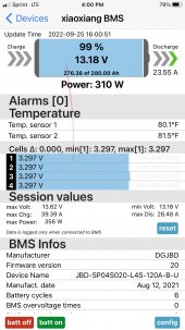
The top balance was stopped at 3.64@ 1.5amps and I had no runners, all cells were within .002 at the end. The screen shot was as I started the draw down the day after the top balance. Mine are mobile as well and used every day.Balance at that voltage level is pretty easy to achieve. When the battery voltage surpasses 14.0 or 3.5Vpc, then see where they're at.
The issue for top balance is at high-knee, when the battery is full, and one or more cells reaches over 3.65Vpc.
Alternatively, at near zero SOC, where one or more cell is completely depleted and falling off in voltage.
My Docan-sourced cells look like yours throughout the whole charge range, however as the cells charge past 3.55 one or more will start to run. I set charging voltage at 14.1 or 14.2 CV, and terminate charging at 5% of amp capacity. This keeps them from over-volting and the bms shutting down charging. Active balance on the JBD happens over 3.4Vpc at a delta of 10mV or greater. SCC is set for 14.1 CV boost with a max duration of ten minutes. A high float - 13.6V, supports active loads when present. The battery stays full unless there are larger loads, or after sun-down.
My cells are mobile, so when the unit is stored or parked, a lower SCC parameters settings lets the battery float down to 50-70% SOC.
This is just before finishing the top balance, still drawing a couple amps.
Attachments
The top balance was stopped at 3.64@ 1.5amps and I had no runners, all cells were within .002 at the end. The screen shot was as I started the draw down the day after the top balance. Mine are mobile as well and used every day.
This is just before finishing the top balance, still drawing a couple amps.
Hopefully, the 3.69v displayed on the power supply is wrong.
S Davis
Solar Enthusiast
- Joined
- Sep 25, 2021
- Messages
- 659
It is not, I have about a .005 voltage drop to the cells, at this point they are about 3.64vHopefully, the 3.69v displayed on the power supply is wrong.
I am at 2P16S, on a single JBD BMS. The 200ma passive balance doesn't quite cut it since different cells ask for balancing depending on charge state. But your experience suggests my distributed dump scheme could back off from the 5A I postulated. Putting a 1 or 2 ohm resistor across my worst problem cell for a few minutes would verify.The top balance was stopped at 3.64@ 1.5amps and I had no runners, all cells were within .002 at the end. The screen shot was as I started the draw down the day after the top balance. Mine are mobile as well and used every day.
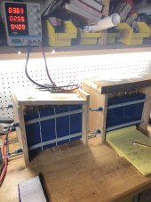
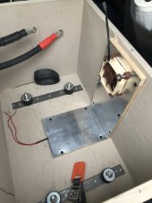
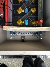
I have a similar scheme for the compression pack. However, I am 16 cells long and 2 cells wide. Each end is 3/4" plywood, reinforced with two horizontal runs of angle iron, drilled out for the rods. Have 6 such rods, two down the middle using red 80x30mm die springs, the four outside rods each under half the tension using yellow 80x30mm die springs. https://www.amazon.com/gp/product/B07GSNCYNK Ends are high enough to mount the BMS plus heavy lugs for power to the inverter/charger on the inside surface of those 3/4" end plates. A piece of fire proof cementboard across the top to keep tools from falling in amongst the terminals. A 600A fuse (came with the BMS) at the positive end of the series string, can't be in the middle or it will interfere with the cell voltage readings that the BMS sees. (Also have a 175A breaker up by the inverter.)
Not obvious what your two bottom rods without the die springs are doing. I just put everything on a plywood base. Am using materials at hand, welded short 1/2" bolts to 1/2" rebar for the rods, far end of the rebar is drilled out for a pin and washer.
I wasn't planning on a darlington pair of NPN's, they would not have collectors tied together. The one up front would have a separate collector resistor to Vcc. Your PNP up front would also work.Don't want the voltage drop of Darlington, instead use PNP to pull up the gate.
Last edited:
S Davis
Solar Enthusiast
- Joined
- Sep 25, 2021
- Messages
- 659
The cells rest on the two pieces of all thread on the bottom, this gives me heating and cooling space below the cells when mounted to my vibration dampers.I am at 2P16S, on a single JBD BMS. The 200ma passive balance doesn't quite cut it since different cells ask for balancing depending on charge state. But your experience suggests my distributed dump scheme could back off from the 5A I postulated. Putting a 1 or 2 ohm resistor across my worst problem cell for a few minutes would verify.
I have a similar scheme for the compression pack. However, I am 16 cells long and 2 cells wide. Each end is 3/4" plywood, reinforced with two horizontal runs of angle iron, drilled out for the rods. Have 6 such rods, two down the middle using red 80x30mm die springs, the four outside rods each under half the tension using yellow 80x30mm die springs. https://www.amazon.com/gp/product/B07GSNCYNK Ends are high enough to mount the BMS plus heavy lugs for power to the inverter/charger on the inside surface of those 3/4" end plates. A piece of fire proof cementboard across the top to keep tools from falling in amongst the terminals. A 600A fuse (came with the BMS) at the positive end of the series string, can't be in the middle or it will interfere with the cell voltage readings that the BMS sees. (Also have a 175A breaker up by the inverter.)
Not obvious what your two bottom rods without the die springs are doing. I just put everything on a plywood base. Am using materials at hand, welded short 1/2" bolts to 1/2" rebar for the rods, far end of the rebar is drilled out for a pin and washer.
Attachments
Could be my 200ma passive balance is sufficient, and all I need to do is increase the voltage at which the balance engages. The system spent a lot of time at 3.4v per cell (or less) due to cloudy weather, and that would definitely contribute.I am at 2P16S, on a single JBD BMS. The 200ma passive balance doesn't quite cut it since different cells ask for balancing depending on charge state. But your experience suggests my distributed dump scheme could back off from the 5A I postulated. Putting a 1 or 2 ohm resistor across my worst problem cell for a few minutes would verify.
Hedges
I See Electromagnetic Fields!
- Joined
- Mar 28, 2020
- Messages
- 20,906
Dumping all power into the NPN is a possibility, but makes for a more expensive NPN. A 25W wirewound resistor can be had from Mouser for a dollar. Just switching the NPN on or off is kind of crude, but I see no reason it would not work.
I think silicon is cheaper than nichrome or whatever these days.
But you will have to try harder not to burn it up. Good choice of resistor and power dissipation is limited. Transistor turned on too hard would melt. I've used PTC resistor to adjust bias of a transistor, but that thing (an 0805) cost me a buck.
Here's an NPN, 40W 7A $1.02 in 10-piece quantity. It will need a heatsink, but so will that resistor.
6A $0.82
Last edited:
SolaroSsaurius
New Member
- Joined
- Aug 27, 2022
- Messages
- 171
Hi!The top balance was stopped at 3.64@ 1.5amps and I had no runners, all cells were within .002 at the end. The screen shot was as I started the draw down the day after the top balance. Mine are mobile as well and used every day.
This is just before finishing the top balance, still drawing a couple amps.
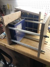
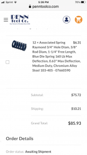
Could you please send me a link to the springs you used in your fixture?
The picture's right battery seems to show them almost bottoming out, or is it just the photo's angle?
Thanks in advance
S Davis
Solar Enthusiast
- Joined
- Sep 25, 2021
- Messages
- 659
These are what I used, they are all set at .63 inches for 160psi each it is just the angle of the photo.Hi!
Could you please send me a link to the springs you used in your fixture?
The picture's right battery seems to show them almost bottoming out, or is it just the photo's angle?
Thanks in advance
Attachments
At some point it might be worth considering getting another BMS (and fuse) and splitting your battery to 16S2P. Advantages are better balancing, double the current capability, and the ability to take one battery offline for maintenance while the other one keeps working.I am at 2P16S, on a single JBD BMS.
Similar threads
- Replies
- 4
- Views
- 280
- Replies
- 11
- Views
- 1K
- Replies
- 14
- Views
- 647
- Replies
- 33
- Views
- 2K