NightStorm
New Member
No idea if this is of any interest but figured I'd come back and update the record here.Finally enough stuff came together that I was able to complete this seemingly endless project. The below is what I've wired up:
View attachment 152732
The idea of the circuit above is to use the capacitors in the mower to delay enabling a relay turning on and off the contactor in the mower. It seems that the key enables a 48 to 12v converter which then turns on the contactor relay. I don't know that the actual circuit in the mower is the way I have it above, it is just my way of thinking about it.
The key has 48v (52-56 actually with the LiFEPO4 batteries) on one side and that enables a path to the 48-to-12v converter. I disconnect the later and run it through a relay so that the 48-to-12v only gets turned on when the relay closes. In my wiring the key enables a path through a resistor (plus diode) that goes to the mower side of the contactor. When the key is turned on it slowly brings the capacitors up in voltage and eventually it reaches a level where the relay can fire. The purpose of the diode is to prevent the closing of the contactor from keeping the relay engaged (the other diodes across the relay coil is just good practice to keep the collapsing field of the relay from sending a reverse voltage spike into the circuit .. you will notice that Ryobi has one across the contactor relay coil). I've wired this up and there is about a 3-5 second delay after I turn on the key until the mower's contactor "clunks" into place and turns on the mower. When I turn off the key the mower shuts down immediately and then about 3-5 seconds later I can hear the relay that I added disengage.
The astute here may recognize a problem that I did not pre-think and rather found during testing. If you turn off the mower and then turn the key back on again prior to the relay turning off the capacitors in the mower won't have been brought back up to voltage and instead the contactor will immediately engage, look like a short to the battery, and the battery's BMS will shutdown. Argh. I am sure there is an elegant solution but I'm tired of working on this, the lawn has gotten too long .. for now I'm just going to be careful.
One other thing: in the above I show a 200 ohm resistor for the pre-charge leg. In my build I actually used 167 ohms 'cause I was cheap and ordered a 10-pack of 5w/500 ohm resistors. I put three in parallel for the "200 ohm" part (making 167 ohms) and two in parallel for the 250 ohm part that feeds the relay.
With that said, the parts I used are these:
Relay
Resistors
Diodes
With that relay you probably don't want to change the 250 ohm resistor much. The relay has a coil resistance of 86 ohms so the 250 ohm resistor makes the voltage across the relay max out at about 52 * 86 / (86+250) or about 13.3 volts.
FWIW I was hoping to use this relay instead of the DPDT one linked above. It is a 48v SPST relay, I experimented with it, but alas did not have on hand the resistor I'd likely need to make it work. As I said, the grass is getting long and the wife unhappy.
I like the second relay 'cause it has a coil resistance of about 1.25k ohms. The problem with it is that cuts in at some very low voltage, significantly lower than the 48v for which it is rated. In addition it cuts out at an even lower voltage, something on the order of 10v. This means it will need something on the order of 2-4k ohm resistor in series to drop the voltage enough to make it effective (I did not have that and observed it had like a 15-20 second on/off delay).
One concern I have is that I don't know what the current rating is for the key switch. Perhaps a painful lesson will follow.
If anyone is interested I can post pictures later of the actual hook-up. Right now I should get to work.")
I simplified my original hookup today. The one above was my "Murphy build": worked 100% through all my testing right up until I got all the skins back on the mower and a full charge in the belly of the new battery. Then it got "finicky". I was too lazy to chase it down and instead just tolerated having to make multiple key-off/key-on attempts getting it started. Wish this simpler mechanism had occurred to me earlier. But it did not.
The simpler circuit looks like this:

Good news is this one is skins-on tested. Full battery too! It uses the alternate relay I mentioned before, a single 200 ohm 5W resistor, and one diode. The circuit uses the parallel resistance of the 200 ohm resistor and the relay to pre-charge the capacitors in the mower. That in-rush current causes the relay to close until sufficient voltage builds up in the capacitors to where there is nothing significant across the resistor. While the relay is closed it disables the voltage going to the 48-to-12v converter (which is what feeds the contactor in the mower), therefore the contactor does not activate. You need the 200 ohms across the resistor because the relay has a resistance of 1.2k and yes, that would precharge the caps but you'd be waiting quite a while. The 200 ohms speeds this up and that particular relay has a very low drop-out voltage so it all works. The diode prevents feeding back through the relay / resistor to the 48-to-12v converter when the key is turned off.
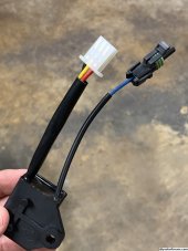
Below is a picture of the relay (the black is not a burn, I had it wrapped in electrical tape and figured I should remove that for the picture .. mistake as it left an ugly mess). You can see the 200 ohm resistor spanning the relay coil (yellow and white leads). The yellow and black are joined and go to the key switch. The white has the diode (inside the red shrink wrap) and the other side of that goes to the tractor side of the contactor. The blue is the normally closed and it goes to the wire that was removed from the key switch (this feeds the 48-to-12v converter that turns on the contactor). Red is not connected. I used automobile style connectors on everything, you can see one at the end of the blue wire.
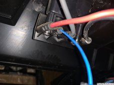
I also today installed a meter (you can see it just below the relay in the photo). This requires a plus feed from the battery to the shunt block
I've been reading that many don't seem to need the precharge. This was not the case for me and my battery seems really, really sensitive to that in-rush current. This works for me and I'm putting it here for the record (and am hoping I don't need to update it again).

Last edited: