diy solar

diy solar

SOK Troubles (user error)

@HighTechLab Nicely done on the video, and excellent visual on what I described.

Despite planning to use tier-1 Outback charge controllers, I'm still looking at this as a point of failure, especially as two or more SCCs are in the system, any one of which failing the wrong way could cause this, and thinking an extra watchdog in the system seems like a worthwhile idea. If my latest comments in the other thread pan out, I think we're looking at $100-$200 to put in a system that provides an extra failsafe in this situation.

@jharrell While it might be nice to prove out the over current, I'm comfortable the voltage test shows it works as advertised. Overcurrent is just the BMS monitor saying to the system "Hey, the charger is putting out too much current. Turn off the flow," which is just what it did in the above overvoltage test: That SOK BMS was just shown to be a, if you will, 50V dam. Doesn't matter whether that 50V can push 2A or 2000A, much like a 50' wide dam 50' high doesn't care whether it is holding back a two acre lake or a 2000 acre lake - the pressure is the same either way. The only difference is how much damage can be done in case of failure.
 
I'm not sure how to pull this one off. I have 2* 8v / 225A power supplies, I could put them in series but I think 225a is not enough. In parallel @ 450a is much better, but with only 8v to work with, it gets tricky trying to push 14v @ 450a (6.3kw)
Well SOK lists 50 amps max charge 100 amps max discharge however I know the overcurrent limits on my 206's are above 110 amps charge / 140 discharge and Min from SOK gave some info to Cinergi here that the BMS is actually rated fro 150 amp continuous charge/discharge and would only cut off after about ten minutes above that. Would be nice to push it above 150 amps and get it to disconnect both charge and discharge and really see what its set for and if it can hold up to the 150 continuous. The cells should be able to handle 1C so a 206 should be able to do it or your big power supplies. I would push my 206's further for testing but I don't have any spares :).
 
Last edited:
Again- while the bms will blow, I think one or two little devices even available on amazingon that trigger a high-rated mechanical contactor could be used to disconnect a failed bms circuit if an install is deemed to require this additional safety layer. Almost like a fuse: it ain’t ever gonna blow except if’n sumpin bad happens. Then you’ll be glad ya spent the money like a one-payment insurance policy that is resettable.
 
I just tested the overcharge protection by applying voltage to a fully charged 12v battery. I was at 50v when the battery could no longer protect itself. The BMS failed closed because one of the FETs broke down internally and short circuited. My shop now smells awful.
Anybody have a theory why an 85v rated FET failed at 50v? Cheap FET or maybe gate voltage?
 
Anybody have a theory why an 85v rated FET failed at 50v? Cheap FET or maybe gate voltage?
My understanding is that 85v is the absolute maximum. Elsewhere in the spec it's defined differently. Essentially the sheet is saying it will fail EVERY TIME at 85v, guaranteed. Also, I suspect gate voltage was super high as that is a derivative of the voltage across the BMS.
 
FETs sometimes die.
If that FET is the only thing separating PV side from battery side in a SCC then it is like you wire the battery directly to the PV string (+diode against reverse flow).
No fuse will protect you since PV generates the usual (or less) Amper.
This is not the first MPPT short error. Not even on this forum :)
Exactly. When an SCC fails, the charge (volts) from the PV is not controlled or limited, and no battery can survive this overcharge. The BMS can handle the “normal” charging from a working SCC, an AC to DC charger or a DC to DC charger, and it will protect the battery in this setting.
Don’t blame SOK; the SCC failure caused the explosion. The SCC’s warranty may be limited to it and not extended to your electrical system, but the SCC co’s liability would not exclude personal injury.
 

Good test :)
But with the 50V I have a problem too.
If you use it 4s then it will be higher than 50V.
So that FET should not pop in 50V. Not even on 70-75V.
Strange.


Part of the challenge in designing a safety disconnect is we don't even have a reliable characterization of rate of voltage rise when SCC shorts PV to battery. I'm not sure it even can be reliably described. I believe the current best theory is SCC shorts PV to battery through working BMS. Battery sinks current to hold PV voltage to battery, until voltage rises to BMS cutoff. Battery line voltage than quickly spikes to PV Voc, fries BMS, which brings the unprotected battery online again, which goes back to holding PV voltage to battery, rising slowly or not so slowly until the cells overpressure and vent.
Good description of the failure. :)
One small addition:
The FETs do not blow because the battery V rises.
The FETs blow when the BMS wants to stop charging, opens the charging FETs.
And the MPPT side the FETs are faced with PV voltage.
 
Again- while the bms will blow, I think one or two little devices even available on amazingon that trigger a high-rated mechanical contactor could be used to disconnect a failed bms circuit if an install is deemed to require this additional safety layer. Almost like a fuse: it ain’t ever gonna blow except if’n sumpin bad happens. Then you’ll be glad ya spent the money like a one-payment insurance policy that is resettable.

A 200A contactor/relay is not cheap.
It can also fail.
Andy had to experience it too


So a simple solution would be a BMS built in crowbar circuit (battery side)
Activates if outer V (MPPT side) rises over threshold (charging FETs are already open) or if FET fails.
And an (inner) fuse to the battery side. To blow and so disconnect the battery.
This battery side fuse is important for crowbar to work.
We all use fuses but mainly after the BMS (me too because V drop on it).
This should be before the BMS.


That reminds me. I have update the Epever MPPT blow up MPP Solar inverter + LFP pack thread.
Did some test and could replicate error.
 
Good description of the failure [TorC]. :)
One small addition:
The FETs do not blow because the battery V rises.
The FETs blow when the BMS wants to stop charging, opens the charging FETs.
And the MPPT side the FETs are faced with PV voltage.

Fair point. When I wrote it I was picturing the DC bus, which I think should have been obvious enough. Nevertheless, I've struck and edited to ensure it hopefully can't be misunderstood.
 
Really enjoyed the video. It gives a very good visual description to what Will and others have been saying for a while now. I don't know if it is possible, but it would be interesting to see what the "safety margins" are on common BMS units, eg. Jk, Overkill, etc. Naturally, going with a higher quality SCC is helpful. However, as users design their panel designs, they might consider configurations that do not go over those limits if possible as a second layer of protection. Again, this may not be reasonable for many applications but it could be a consideration for some. Of course the challenge here is the cost of wiring which may be prohibitive.
 
Last edited:
Yikes, quite a lot of bad information in this thread. Where should I start. First off, the sok is not special, even UL listed batteries for medical/military application will still be destroyed by high voltage. There is a limit to any OVD circuit. I don't think sok or any company should be responsible for this. There is over voltage protection within the working voltage range of the battery, and a fet based BMS accomplishes this well.

In marine application, alternator regulator failure leading to high voltage has destroyed any battery on the market. Battleborn, valence, sok etc.

Even if you use a fortress battery, simpliphi or discover battery (top of the line lifepo4), they will all be destroyed by high voltage, and I personally don't think it's fair to honor these warranty claims.

The individual should be responsible for these types of failures. I've had over voltage from transformer based chargers and I've destroyed BMS in the process. Did I blame the company? Absolutely not. It was MY fault, and no one else. Using these batteries can only be done in the way they are designed to be used. If you use cheap mppt and it fails, that's on the user. Not the company.
As some one who works for an electronics manufacturer in the solar industry I was shocked myself when I learned a ways back that no BMS would really protect you in an over voltage situation. It was brought to our attention by a couple of the largest names in the lithium market that when a 600v MPPT fails bad things happen. For this reason Midnite has designed in a fail safe circuit that will trip the pv breakers if the battery voltage exceeds a safe voltage. Hopefully more will follow this lead or we can all work to find a better over voltage device?
 
As some one who works for an electronics manufacturer in the solar industry I was shocked myself when I learned a ways back that no BMS would really protect you in an over voltage situation. It was brought to our attention by a couple of the largest names in the lithium market that when a 600v MPPT fails bad things happen. For this reason Midnite has designed in a fail safe circuit that will trip the pv breakers if the battery voltage exceeds a safe voltage. Hopefully more will follow this lead or we can all work to find a better over voltage device?

Good inverters have galvanic isolation between battery and PV. Between battery and 400V DC BUS really :)

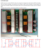
This is the Axpert VMII (original, not clone).
Also I think it is the same in VMIII, so in MPP Solar MG, MGX, GK.
You have to check the US version :) (also in the Growatt).


VMII_2.png


So the battery is isolated with highV highFreq transformers from 400V DC BUS.

Clones like EASun and others (some types) do not have the same inner structure.
In many cases the transformer is missing and they have a secondary DC BUS in battery V.
So MPPT without galvanic isolation directly connects to this battery DC BUS. As does the battery.


Here is the even more robust MPP Solar MPI Hybrid (alias Voltronic Infinisolar) 10kW real hybrid with two isolated 5kW buck-boost converter.

MPI_hybrid_10k.png

So in both inverters the battery 48Vdc is converted up to 400Vdc.
Battery power first converted to a high freq AC.
It goes through the transformer (galvanic isolation).
Made again into DC and V is converted up and smoothed.
 
Could you put a Victron battery protect in between the output of the SCC and the batteries? It says in the data sheet it has over voltage protection.


Although reading the manual, if you hook it up to something that supplies voltage, it will be damaged. So maybe a diode on the output terminal so it doesn't see current from the battery on the output terminal.

Nope won't work because the SCC won't power up.

How do I delete a post?
 
Last edited:
Good test :)
But with the 50V I have a problem too.
If you use it 4s then it will be higher than 50V.
So that FET should not pop in 50V. Not even on 70-75V.
Strange.


Good description of the failure. :)
One small addition:
The FETs do not blow because the battery V rises.
The FETs blow when the BMS wants to stop charging, opens the charging FETs.
And the MPPT side the FETs are faced with PV voltage.

In a 48v system, one battery won't have 50+v on it's terminals...The other 3 batteries don't go short-circuit and provide full voltage from the charge source to the shut down battery. If there was 60v on the 48v main terminals, if the other 3 batteries were at 14v, then the 4th battery would be at 18 volts. Still well below 50v. Your 48v main terminals would need to be upwards of 90v for the 4th battery to see 50 volts, in the same manner that it was applied in the video. Most 48v systems never go above 64v (the point of major component failure).
 
In a 48v system, one battery won't have 50+v on it's terminals...The other 3 batteries don't go short-circuit and provide full voltage from the charge source to the shut down battery. If there was 60v on the 48v main terminals, if the other 3 batteries were at 14v, then the 4th battery would be at 18 volts. Still well below 50v. Your 48v main terminals would need to be upwards of 90v for the 4th battery to see 50 volts, in the same manner that it was applied in the video. Most 48v systems never go above 64v (the point of major component failure).

I am just thinking out loud ...

Lets separate the problems:

1, 85V MOSFET pops at 50V. I do not think it is OK.

2, can be 50V in any BMS any BMS leg ?

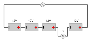
When discharging:
Battery_serial.png
Battery_serial_2.png


And now replace the load to a charger.
Like MPPT charging 3,65V * 16 = 58,4V

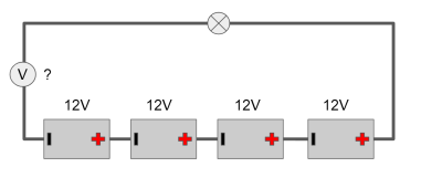
The BMS is in the (after the) - pole of the battery (draw it separated this time).
What Volt would have the leftmost battery's BMS have ?

Battery_serial_3.png
 
85V MOSFET pops at 50V. I do not think it is OK.
This is the source-drain voltage, keep in mind the control circuit could also be providing more voltage on the gate in the overcharge situation...You must consider the whole BMS not just the FET.

Battery_serial_3.png
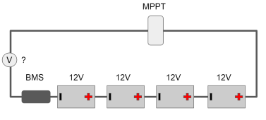
Let's say MPPT = 60v for conversation sake. Each battery would be at 14.6v because they are full at OVP.
V? = The MPPT is the voltage source.
60-14.6-14.6-14.6-14.6 = 1.6v across the terminals of the BMS. Each battery subtracts since they would be accepting the charge.

@smoothJoey @Hedges @FilterGuy Am I thinking clearly???
 
Really good response here, great to see quality service and education going on in other companies.

Keep any spark potential away for the cells if anybody tries this personally as the gases are flammable.
 
So to continue to think out loud. Suppose one has a 24v system with 2 or more batteries in parallel. They decide to place 41 volt solar panels in series with 2 per series.

Naturally a charge controller would be in place. This question is based on the premise that the SCC failed.

Now factor in a clear cold sunny day. Earlier discussions recommend a 1.25 factor with voltage. Would 41 x 1.25 push a typical BMS (e.g. Overkill) into failure mode?

Thanks
 
Back
Top