diy solar

diy solar

Sol-Ark 15K All in One Inverter Released.

I'll chime in here as I have a Sol-Ark 15K with an AC-Coupled portion of my panels tied into the gen terminals.

Notice, the settings for the SmartLoad (ie Gen) terminals are under the battery setup.
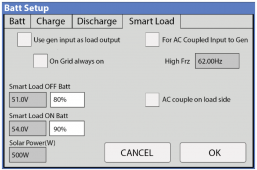
Screen Shot 2022-10-13 at 3.15.49 PM.png

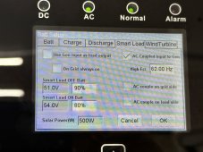
The way this handles my SMAs are that upon grid failure {if my batteries are above the Smart Load OFF Batt setting}, it immediately opens the relay and/or bumps the freq to 62 Hz and kills the AC-Coupled inverters. The SMAs can easily shut down fast enough, but what I don't know is if the Sol-Ark has to dump power to the batteries in the process. Also, the DC-coupled solar keeps on trucking (albeit possibly curtailed depending on house load). If the battery level drops below the Smart Load ON Batt setting, the relay closes for the Gen breaker and the SMAs begin their 5-min countdown until they begin producing again. If the grid returns anytime the AC-coupled inverters are disconnected, the Sol-Ark will close the relay and the SMAs will again perform the 5-min countdown before resuming PV production. As far as the SMAs know, the grid failed and therefore UL1741 means I must hold back.

Now, I know Enphase can do fancy stuff with the microinverters as far as limiting export, but I'm not sure how the Sol-Ark can handle that on the Gen port. Especially not without batteries to buffer the power. And how would the Enphase inverters handle the UL1741 countdown? If the Sol-Ark opened the Gen port relay, I would assume Enphase would assume the grid failed as well.

In summary:
  • AC-coupling appears to need the battery. If no battery, just land it on the grid side.
  • Sol-Ark has no ability to throttle AC-coupled
  • AC-coupling is nice and provides redundancy, but DC-to-DC is much betterer {of my 18kw, ~12kw is DC-coupled}
And sorry if this didn't really answer the question, but this was confusing to me when I installed and took a bit of observation to figure out exactly what it was doing.
 
Last edited:
The SMAs can easily shut down fast enough, but what I don't know is if the Sol-Ark has to dump power to the batteries in the process. Also, the DC-coupled solar keeps on trucking (albeit possibly curtailed depending on house load)
What I have noticed with my Outback Skybox is in that scenario the DC gets curtailed immediately because the AC coupled Enphase IQ7s have a slow ramp down rate because of CA Rule 21 (same as UL1741SA). Then once things stabilize to the load the DC coupled solar gets priority but I don't have details. Yes, if there is excess power it has to be dumped to batteries since they are the only buffer until the Enphase can ramp down. The slow ramp is a requirement of CA Rule 21 for grid stability. If I understand the SolArk correctly they use the Gen port so that worse case the relay can open and AC coupled inverters will essentially be offline immediately if needed.
Do you know if your SMAs are generic UL 1741 or the new version with the SA suffix?
 
Last edited:
What I have noticed with my Outback Skybox is in that scenario the DC gets curtailed immediately because the AC coupled Enphase IQ7s have a slow ramp down rate because of CA Rule 21 (same as UL1741SA). Then once things stabilize to the load the DC coupled solar gets priority but I don't have details. Yes, if there is excess power it has to be dumped to batteries since they are the only buffer until the Enphase can ramp down. The slow ramp is a requirement of CA Rule 21 for grid stability. If I understand the SolArk correctly they use the Gen port so that worse case the relay can open and AC coupled inverters will essentially be offline immediately if needed.
Do you know if your SMAs are generic UL 1741 or the new version with the SA suffix?
All three are Sunny Boy SB6.0-1SP-US-41. Mine appear to be UL1741/2016/120. No mention of SA. Funny enough, they are in Island Mode by default and output can be controlled by frequencies between 61 and 62Hz. (I’m assuming linearly, but can’t tell). So theoretically the Sol-Ark could control them if that feature was implemented.
 
Mine appear to be UL1741/2016/120. No mention of SA. Funny enough, they are in Island Mode by default and output can be controlled by frequencies between 61 and 62Hz. (I’m assuming linearly, but can’t tell).
That would be early version of 1741 so they are not linear but only on or off which makes them different to manage via frequency Watt..in some ways they are easier because, as you said, they respond quickly. Or it could be the relay on the gen port opening which would give the same result..
 
Ok I have a question.

Server rack batteries have DC circuit breakers, and the Sol-Arks all have DC disconnects, so is a class-T fuse even required? Or can you go 4/0 straight to the inverter?
Definitely not required, although a good fuse might be able to interrupt a higher current than the breakers (I haven't checked the specs on the built in ones).
 
I'll chime in here as I have a Sol-Ark 15K with an AC-Coupled portion of my panels tied into the gen terminals.

If the battery level drops below the Smart Load ON Batt setting, the relay closes for the Gen breaker and the SMAs begin their 5-min countdown until they begin producing again.

Is that picture your screen? Or do you have "For AC coupled input to gen" checked?

With nothing checked and voltage/Soc shown, appears to match how a load should be controlled, backwards of how a source should connect.
It also wouldn't support having AC coupled sources backfeed grid while battery was full.
 
It also wouldn't support having AC coupled sources backfeed grid while battery was full.
I am not sure which setting you are referring to that would not sell to the grid. If you are talking about a scenerio when the grid is down I would hope the internal transfer switch would prevent backfeed.
 
What I meant was, if SolArk is configured to only close the "gen" relay when battery is below 90%, then in general when grid connected and battery full, the AC coupled Sunny Boys on gen port would be disconnected.
(based on the screen shot shown.)
 
Is that picture your screen? Or do you have "For AC coupled input to gen" checked?

With nothing checked and voltage/Soc shown, appears to match how a load should be controlled, backwards of how a source should connect.
It also wouldn't support having AC coupled sources backfeed grid while battery was full.
That’s from the manual. Here’s mine. Fair warning that taking a picture of the LCD screen sucks.

IMG_0148.jpeg

Quoteth the manual:

AC Coupling Settings (" For AC Coupled Input"):
  1. To use the Gen input breaker as an AC coupled input, check the "For AC Coupled Input to Gen" box (this feature will also work with "Grid-Tied" Inverters.
  2. The meaning of Smart Load OFF Batt and Smart Load ON Batt change in this mode
Smart Load OFF Batt: The SOC at which the AC coupled inverter(s) are shut down when in off-grid mode (90% recommended)
Smart Load ON Batt: The SOC at which the AC coupled inverter(s) are turned on when in off-grid mode (60%-80% recommended)
 
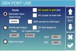
Also found this verbiage in a Deye manual:

Screen Shot 2022-10-13 at 8.40.46 PM.png

AC Couple Fre High: If choosing“Micro Inv input”, as the battery SOC reaches gradually setting value (OFF), During the process, the microinverter output power will decrease linear. When the battery SOC equals to the settng value (OFF), the system frequency will become the settng value (AC couple Fre high) and the Microinverter will stop working.
  • MI export to grid cutsoff: Stop exporting power produced by the microinverter to the grid.
  • Note: Micro Inv Input OFF and On is valid for some certain FW version only
  • AC couple on load side: connecting the output of on-grid inverter at the load port of the hybrid inverter. In this situation, the hybrid inverter will not able to show the load power correctly.
  • AC couple on grid side: this function is reserved.
  • Note: Some firmware versions don’t have this function.
Sol-Ark will have to chime in to say if the Sol-Ark has this function or if it's all or nothing.
 
What I meant was, if SolArk is configured to only close the "gen" relay when battery is below 90%, then in general when grid connected and battery full, the AC coupled Sunny Boys on gen port would be disconnected.
(based on the screen shot shown.)
Yes that would be a poor design. At least they used the gen port to cut off the AC coupled inverters. If they had cut off power to the AC out port the whole concept of back up would have been down the drain.
 
@12kw_2021
In the meantime I presume your Enphase worked when connected to your main panel since the AC passed through to that. One you get your PTO that should work to use your micros until you get batteries connected and can use the Gen port for AC coupling.
Hello... Yes.. I provisioned the Enphase array, and all 30 panels work, I just had the local inspector sign off, He insisted I need one ground rod at the array, so I need to add that, once I send him pictures of the new ground rod he will sign off on the paperwork the local power company needs. Still going back and forth with the paperwork with them. The enphase inverters, AND the Solark inverters made them very confused. Hopefull that will get straightened out soon. In the meantime I will build my first 48V battery, and connect, then I can effectively use the Solark.
I am now fully aware that the "inverter" really doesn't do much unless you provide a DC source to invert. Live and learn. Thanks to all (well mostly all) who are helping. I am doing all the work myself, and learning a lot so thats fun, and I am saving a lot of money in the meantime having fun
 
Solark Tech support confirmed that if/when you have no DC input source connected (DC PV, or DC batteries) the current software has no ability to send 240V to the gen pins, and the AC coupled option do not work. The only solution is to disconnect the AC Solar, and connect to your panel and backfeed, then the Enphase inverters see 240V, turn on and generate power. They did mention the Ac coupled on Load side option, but indicated it would not add much value. So for now, I am leaving the AC coupled PV connected to the gen port and planning a 16 cell battery build next week. I have the cells, just need the 2/0 wire, and some polaris connectors to connect the BMS wires to the large 2/0 cable.

Conclusion: Sol-ark 15K is an inverter and default expect a DC input source (PV, or batteries) If you don't provide one, don't expect it to do anything, because it will not. Connecting AC coupled PV is a waste of time , without a DC input as well.

Thanks to all who chimed in , I am still learning, and the Sol-ark will still be a nice addition to my homestead, I just need to get DC source connected. (And of course get the local electricity supplier to accept my complicated paperwork).

CPU
 
On other advantage is the efficiency. DC coupling is more efficient charging batteries. AC charging is slightly less efficient due to internal loss going from AC to DC then back to AC. PV charging DC to batteries then back to AC. One less step.
 
On other advantage is the efficiency. DC coupling is more efficient charging batteries. AC charging is slightly less efficient due to internal loss going from AC to DC then back to AC. PV charging DC to batteries then back to AC. One less step.
Technically its more, panels are originally DC, then micro inverters to AC, charger converters back to DC, then inverter back to AC. So many unnecessary conversions!!!
 
On other advantage is the efficiency. DC coupling is more efficient charging batteries. AC charging is slightly less efficient due to internal loss going from AC to DC then back to AC. PV charging DC to batteries then back to AC. One less step.
I fully agree but I purchased my panels and the inverters with a covid discount in 2020. If I had bought them now I would have paid 30 to 50% more. I made a decision in 2020 and I still have what I think is a reasonable array but again I agree you're absolutely correct
 
You could add some DC panels (check out SanTan's used selection).
You could put in 4x car batteries from the junk yard, provide starting surge for motors. (If there is a way to shut down without dropping below about 90% SoC they might even last a few years.)

Do your panels have MC connectors between panel and microinverter? If so could repurpose a few for DC.
From what we hear, SolArk will give more stable AC coupling and management of PV production if DC coupled exceeds AC coupled.
Good suggestions. I buried two expansion runs of 10 gauge UF wire in the trench. I have 14 extra ground screws free from unirac (long story).
Next spring I need to get busy expanding with direct DC PV. I considered removing all of the expensive enphase inverters putting them on eBay and just going all DC. But I decided to stay where I'm at. I'm going to start building my 16 cell 48 volt battery today and hopefully by this time next week I'll have a DC of source that makes the solarc happy.
This install has been an adventure. Who knew I needed to relocate my main 200a panel 2 feet to the left and pull New wires from meter to basement to have an install meet code.
Hell 2 months ago I didn't even know what a power distribution block or raceway was.
?. Thanks
 
Got it. I know there are a few differences dc vs ac coupled. You sound frustrated and I understand. Being a grid tied guy for 8 yrs our new Sol Ark is amazing and functioning better than I expected. But that is our experience. Tech support from Sol Ark has also been extremely good.

Now to your battery connections. Here is what I did. I installed two Lynx Power Ins to use as my fusible buss bars. I ran two sets of 4/0 from inverter to the Lynx buss. Landed one set on each end of the busses. Then I ran individual equal length cables from each battery to the buss. I installed 300A 48v mega fuses on each battery positive lead. Works very well and is very safe. Lynx is rated at 1000A. Just my way of doing it.

Here is a way to save $50-60 over the Lynx distributors.
Hello.. Thanks I like the hack... the only Mega fuses I find are all rated for 32V. Example below.. Suggestions or link please? Thanks for clarifying

32 V version
 
I fully agree but I purchased my panels and the inverters with a covid discount in 2020. If I had bought them now I would have paid 30 to 50% more. I made a decision in 2020 and I still have what I think is a reasonable array but again I agree you're absolutely correct
On the plus side panels are relatively cheap so these losses can be compensated for. I’ve not worked with any other brand but if some of the stuff I’ve read is true some brands have efficiencies down in the 70% range while others are in the 90% range. Big differences. I’m still analyzing my data. For instance I think overall (don’t hold me to this) I’m seeing about a 12-15% loss overall on my stored energy (batteries). Hard to nail down precisely as PV charging is more efficient than grid charging. That’s counting the energy charged vs the energy discharged. This is new to me but I think I’m pretty close. My PV production numbers are probably 95-97% efficient. My original panels are now 8 yrs old so I’m having some age loss (hard to be precise because of variants of weather) but it’s not terrible probably 5-7%. What does this tell me… I could benefit from a few more panels next spring to add back in some more production for efficiency losses. It’s all a balancing act. Just a little more money and I can fix that right?
 
Back
Top