diy solar

diy solar

Solar Tracker Design

the PV area x wind force factor & exposure = force per unit area for calculation,
multiply by the projected area of the PV panels (or just use the full area)
lever arm is the length of your column.
base can be designed based on overturning - search foundation design for sign posts.
 
Thanks for the pointers! Sometimes the answer is just out of reach. I had not considered using sign calculations.

I've done some searching and am not finding much good info that isn't behind paywalls.

PV area = 51 sqft (4.7 m2)
Wind force will be far lower than any calculator I found as the array will park when the wind speed increases.

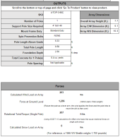
This calculator goes down to 90 mph: https://www.mtsolar.us/top-of-pole-mount-calculator/

When parked, it recommends a 2' square 2.5' deep foundation.
(I had to fudge the array dimensions to get the sqft close, this site requires choosing panels from a drop down. My array is nearly square.)

1685946686598.png

That site doesn't have the option to run calcs at 30 mph (we don't get much during the day, I'll likely park it at something around 20mph)

I found a spread sheet that allows me to type in the wind. Both the spread sheet and website come up with similar numbers with a vertical array (4.5' deep footer @ 90mph)
But the array should never be vertical at 90 mph.
At 30 mph (with a vertical array), it comes up with a 2' square 1.8' deep footer.

Anyways, best I can tell I have two criteria for the footer:
Parked at up to 90 mph, it needs a 2' wide 2.5' deep footer
Fully exposed at 30 mph, it needs a 2' wide 1.8' deep footer (or 1.5' wide by 2.03' deep)

The website I used for calculating the parked array does not support holes smaller than 2' across. But each 1/2' step larger only reduces the depth by 0.2'
By that logic, I could probably use a 1.5' wide hole at 2.7' deep.

The hole currently is 1.5' square and 3' deep.
Best I can tell, that is good enough.
 
The overturning resistance of the foundation relies on both the size of the footing and the soil over it, so the depth of bury is an important part of the design. Suggestion: I am not sure how reliable the 'parking' feature will be, if it fails to park, consider what the consequences will be. Compare this to the cost/effort of just building the slightly bigger/deeper base.
 
I purchased an MT Solar mount for my array. That calculator is close. If you are purchasing a mount they ask for more detailed information such as the max wind rating for the area, soil type and others data, then they will use a sign foundation calculator for the final report.

Do not use data in your calculations that is not the max rating for the area as this will lead to failure down the road.

I can tell you the amount of force on the poles and foundation are quite substantial. This spring with wet ground and not fully settled earth at the array footings, you could see some movement of the pole/foundation. The holes were bored with a 36" earth auger and the pipe inserted and concrete poured around it as they recommend.

How do you plan on digging the square hole? There is a video by MT Solar where they dig using a mini excavator. They recommend filling the hole with concrete is undisturbed soil and no concrete forms.
 
The overturning resistance of the foundation relies on both the size of the footing and the soil over it, so the depth of bury is an important part of the design. Suggestion: I am not sure how reliable the 'parking' feature will be, if it fails to park, consider what the consequences will be. Compare this to the cost/effort of just building the slightly bigger/deeper base.
Good point. The automatic parking feature should be very reliable, it should park every night. To park when windy, it will also need to my wifi network to be up, so the wind data can get from the weather station to the tracker.

I can tell you the amount of force on the poles and foundation are quite substantial.
Agreed, that's why I'm asking questions.
This spring with wet ground and not fully settled earth at the array footings, you could see some movement of the pole/foundation. The holes were bored with a 36" earth auger and the pipe inserted and concrete poured around it as they recommend.
What's th size of your array? Depth and quantity of those 36" footers?
How do you plan on digging the square hole? There is a video by MT Solar where they dig using a mini excavator.
It's a single hole and already 1.5' square by 3' deep. All dug by hand, it wasn't bad because I wasn't in a hurry, so I could do a 20 minutes at a time daily over the course of a week.
They recommend filling the hole with concrete is undisturbed soil and no concrete forms.
That's my plan!
 
8 feet deep. https://diysolarforum.com/threads/mt-solar-mount-review.51255/

It needs ballast for wind. Not only lateral but also uplift.
Just to run the roughest of numbers:
You have 16 panels? My array is tiny by comparison, 2 panels.
You have 16 feet of concrete under the ground (36" diameter)
That's 1' of concrete depth per panel. A better calculation point would be 7 cu. ft. per panel.

If I widen the hole to 2', I'll have 6 cu. ft. per panel, with less exposure to wind and a smaller lever arm (shorter mount pole)
I'll dig a bit deeper when I widen to 2'. Just to gain a little more and get closer to your 7 cu.ft. per panel and closer to the worst case calculations if the array doesn't park.
 
Seems so much easier around here: Auger down 3-feet and then drill & grout anchors into the 3-million square mile footer below - called the Canadian Shield. Seems pretty solid...so far.
An advantage if you're bolting to it but a disadvantage if you're digging it.
Dynamite, anyone?
 
Seems so much easier around here: Auger down 3-feet and then drill & grout anchors into the 3-million square mile footer below - called the Canadian Shield. Seems pretty solid...so far.
Wow, that does sound easier!

I've got nothing but soil down there. I don't think I've even found anything resembling gravel yet.
 
Last edited:
Slow progress is still progress.

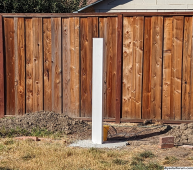
The post is cemented and standing:
1697407769336.png

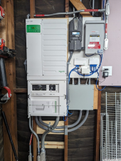
Conduit is run, including in the trench.
The new conduit is labeled "Solar PV DC circuit" enters at the bottom left and loops up around into the combiner at the top right.
1697407871980.png

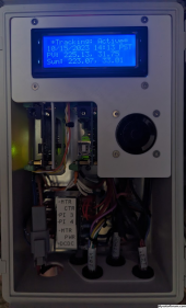
The controller is assembled and coded:
1697408143062.png

I should have the aluminum for the panel frame this week, assembling the tracker frame is the last step.
 
That is so cool you are working on this with your kid!

I hate math even though I can do it if forced.

You might take the post you will be using and make a simple tripod base and set it in the yard where you think you will get the best sun.

Then check it in the morning and evening to see the shadow pattern on the ground and when the mount would get the best sunshine.

Unless you are living near skyscrapers or mountains only the closest homes and trees or objects in the yard are likely to cause shadow issues.

Nice to see another designer and tinker on here and I have been working on a post design for manual adjustment and bifacial panels but if yours works I might consider adding a tracker later.

This is my design so far:

Pole Mount2 - Copy.png Pole Mount1 - Copy.png
 
That is so cool you are working on this with your kid!
Last weekend both kids chose to pour concrete, vs making a trip to the mountain or lake.
I hate math even though I can do it if forced.
Coding is worse than math in my opinion.
You might take the post you will be using and make a simple tripod base and set it in the yard where you think you will get the best sun.

Then check it in the morning and evening to see the shadow pattern on the ground and when the mount would get the best sunshine.

Unless you are living near skyscrapers or mountains only the closest homes and trees or objects in the yard are likely to cause shadow issues.
In early morning, even short objects cast really long shadows. I used www.suncalc.org to visualize the shade cast by trees, fence, neighbors, etc.
It lets me check the shadows year round, vs just checking shadows at this time of year.
That site isn't super intuitive, but it's not the worst and results seem accurate based on the summer results.

Plus the post is already in about 2,000 pounds of concrete, so too late for moving it now.
Nice to see another designer and tinker on here and I have been working on a post design for manual adjustment and bifacial panels but if yours works I might consider adding a tracker later.

This is my design so far:

View attachment 172471 View attachment 172472
Nice, are you building a single axis tracker or dual axis?
 
Coding is worse than math in my opinion.
I am also an Indie game programmer and started on a Commodore 32 in BASIC lol!

No tracker and manual adjustments for spring, summer, fall and winter.

Two versions and one for single axis and one for dual.
 
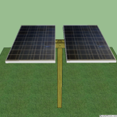
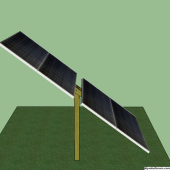
I've spent some time on designing the frame. These are bi-facial panels and I'm trying to keep the framing to a minimum. But I could use some input on both the design and material thickness.

The tracker/slew drive has flanges on each side that rotate to adjust the elevation/vertical.


Bolted to this flange, will be 2" OD (1/8" wall?) aluminum tubes protruding out each side.
The angle pieces the panels bolt to is 1"x3" for the two outers and 3"x3" for the center piece, all 3 are 1/8" thick aluminum.
I suppose I could use four 1"x3" pieces vs the current 3.

I am also considering sliding a tube inside (through the middle) and connecting the 2" pivot tubes to add some bracing/strength.

I guess the question is, do you think the design is strong enough?
Is 1/8" thick aluminum is a good choice?

The panels weigh 64 lbs/29kg each.
Wind loads here are low, it will see some protection by the fence, plus will park flat (below the fence line) when the wind gets too high.

That brings another question, any one have input on what wind speed should I park the tracker flat?

View attachment 150676


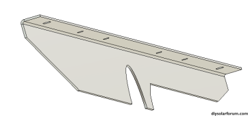
I slightly redesigned the end plates to show how they'd actually be built. I also added all the mounting holes for the panels.
View attachment 150677
Solar Wizard

I am looking to relocate 16 panels (4KW) from my barn roof, which looses the sun around 6.00pm in the summer which initially did not bother me, but with the price of electricity now it seems worth doing.

I am interested it see if you have completed the project, as I am interested in using a slew drive but unsure which size to buy and the structural strength of the frame. I will be locating the system in our field so there are no issues with shade etc.


Thanks
Prime solar hours are 2 hours either side of solar noon (11am to 3pm during DST) so you're not gonna get much at 6pm anyway.
 
Solar Wizard
Not so formal ?
I am looking to relocate 16 panels (4KW) from my barn roof, which looses the sun around 6.00pm in the summer which initially did not bother me, but with the price of electricity now it seems worth doing.
I'd agree with 45north, you might go to the Nrel PVwatts site and download the hourly data for your array. I doubt you're missing out on much production after 6pm
I am interested it see if you have completed the project,
Still in progress. I picked up the aluminum for the panel frame, I just need to cut and weld it all up.
as I am interested in using a slew drive but unsure which size to buy and the structural strength of the frame.
This was my biggest concern, I really didn't know how to calculate it until after I ordered parts. Let me put together some information later when I'm in front of a computer.
I will be locating the system in our field so there are no issues with shade etc.
Excellent.
My last point is that there's almost no return on investment with the current cost of panels, so if you have the room, you will be far ahead to just buy more panels. I could have purchased many kw more panels for what I have into this tracker.
 
Slow progress is still progress.
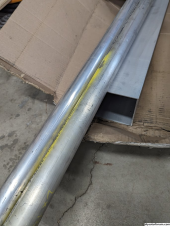
I picked up the metal for the panel frame a while back.
1700010799027.png

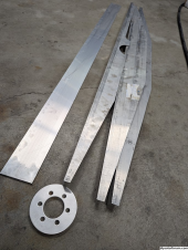
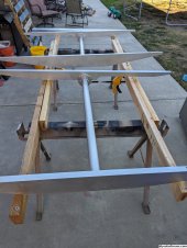
And over the weekend I cut up the pieces. The 3 on the right are all angles. (L shaped with the panel bolted to short side hidden in the pictures)
Welding the parts together started yesterday (as you can tell because I've only got 3 of 4 in this picture)
1700010838322.png

Here's an example from Fusion 360 to show the shape.
1700011102938.png
 
Back
Top