diy solar

diy solar

SunGoldPower Low Frequency Inverter UL1741

automatikdonn

Becoming Offgrid
Joined
Oct 20, 2021
Messages
331
Location
Texas
I am curious about people who have growatt 12k LF inverters. How do you handle the ground / neutral bonding in these units? If they are connected to the grid on L1/L2 and they produce their own neutral - doesn't this break the rules for multiple ground neutral bonds off the same service?

I have no idea how these inverters work, so I am curious.

UPDATE:
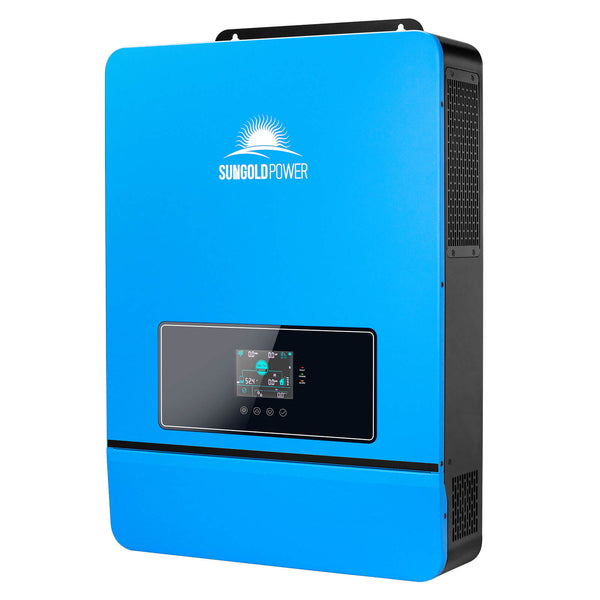
I borked this thread by asking about the Growatt 12k. The unit in question is a SunGoldPower 8k UL 1741 model.

The answer to the question is in this post - https://diysolarforum.com/threads/s...ency-inverter-ul1741.50940/page-2#post-652517

These units do not bond the neutral and ground inside of the inverter from my testing. YMMV, please test for yourself. I am not a licensed electrician.
 
Last edited:
I have no idea how these inverters work, so I am curious.
You have touched on the root of the problem. They don't tell you enough information about internal grounding and bonding to know what to do. It is nearly criminal that *all* of these value-priced AIO inverters completely ignore the grounding and bonding in the documentation.


I assume you are refering to the SPF12000 DVM


Here is how I think they are set up: (Warning: I could be wrong)

1669228407678.png

One interesting thing about this inverter is that there is no Neutral on the AC in. Just the two Hot inputs.

Now let's put it into a system:

1669228597787.png

There are two issues with the above diagram.
1) the output neutral is floating and therefore is not technically neutral (It is not a grounded conductor). It must be considered a hot wire.
2) there is no low-impedance path that will trip the breaker in the event of a ground fault.

Given all of this, the inverter should be considered an independently derived source and there should be a neutral-ground bond on the output.

EDIT: The following diagram is not to code. Please see post #5 for a more code-compliant diagram.

1669228940351.png
WARNING: This diagram assumes my original model of the inverter is correct.


Since the neutral in the main breaker box is totally separate from the neutral on the AC output there is a single N-G bond on each neutral (This does not break the 'Single N-G bond' rule.)
 
Last edited:
You have touched on the root of the problem. They don't tell you enough information about internal grounding and bonding to know what to do. It is nearly criminal that *all* of these value-priced AIO inverters completely ignore the grounding and bonding in the documentation.


I assume you are refering to the SPF12000 DVM


Here is how I think they are set up: (Warning: I could be wrong)

View attachment 121546

One interesting thing about this inverter is that there is no Neutral on the AC in. Just the two Hot inputs.

Now let's put it into a system:

View attachment 121547

There are two issues with the above diagram.
1) the output neutral is floating and therefore is not technically neutral (It is not a grounded conductor). It must be considered a hot wire.
2) there is no low-impedance path that will trip the breaker in the event of a ground fault.

Given all of this, the inverter should be considered an independently derived source and there should be a neutral-ground bond on the output.

View attachment 121550
WARNING: This diagram assumes my original model of the inverter is correct.


Since the neutral in the main breaker box is totally separate from the neutral on the AC output there is a single N-G bond on each neutral (This does not break the 'Single N-G bond' rule.)

So what you are saying is they have the same issue as the autotransformers and GW5KES setups do.

NEC states that a grounded conductor must be electrically connected with the generated leg. So in this case you have to pull a neutral from the main panel into the sub panel.

Thanks for the response, I have a sungoldpower 8k LF showing up on Friday, so I just kinda wanted to know what I got myself into.

I plan to connect the output from the inverter to a reliance controls pro/tran2 to solve this bonding issue.
 
So what you are saying is they have the same issue as the autotransformers and GW5KES setups do.

Not if it is a true isolation transformer in the unit. I believe Filter Guy asked GW but never received a response.

NEC states that a grounded conductor must be electrically connected with the generated leg. So in this case you have to pull a neutral from the main panel into the sub panel.
No, it is to be considered separately derived and requires a N-G bond in critical loads panel after the inverter such as the last diagram above.

That is, if it is a true isolation transformer internally.

Thanks for the response, I have a sungoldpower 8k LF showing up on Friday, so I just kinda wanted to know what I got myself into.

I plan to connect the output from the inverter to a reliance controls pro/tran2 to solve this bonding issue.
Beware that only a few of the Reliance transfer switches have neutral switching. This is important as you will need a N-G bond but can't have 2 when the system is grid powered.

Put up the model # and a wiring diagram on how you intend to install this.
 
So what you are saying is they have the same issue as the autotransformers and GW5KES setups do.
It is certainly very similar.

NEC states that a grounded conductor must be electrically connected with the generated leg. So in this case you have to pull a neutral from the main panel into the sub panel.
This implies you are not allowed to recreate a neutral using an auto-transformer. I can kinda see why they would say this. Could you point me to the part of NEC that says it? (I am not arguing, I just want to learn.)

If a Neutral is pulled from the main breaker box to the critical load breaker box it would look like this:

1669248316655.png
Reminder: I am not 100% sure my model for the inverter is accurate.... but it is my best guess based on what everyone on the forum has told me.
(There are other possible models that Could have significant implications on how the system should be wired.)

Notice that there is no NB-Bond in the critical load panel.

I guess that would work. In both cases, the neutral output is a grounded conductor, so it is unclear how the inverter would know the difference between the two diagrams. However, with this set-up the output transformer will try to balance the two legs for everything back to the utility transformer when in pass-through mode.

The interesting thing is that this is essentially what I have been calling a common-neutral arrangement. (The grid neutral is the same as the neutral out of the inverter.) This would also mean a transfer switch between the inverter and the critical load box would not have to switch neutral.

Note: I feel more comfortable about using this inverter in a common neutral set-up than I do the ones that have a neutral-in. The inverters with neutral-in would have neutral-in and neutral-out tied together in a common neutral set-up and I do not know if it is supported or if there are any implications beyond the concern of the output transformer trying to balance the two legs of the whole circuit back to the utility transformer.. If designed properly, the inverter will cut out if the load imbalance gets higher than it can handle.
 
210.9 Circuits Derived From Autotransformers
Branch circuits shall not be derived from autotransformers unless the circuit supplied has a grounded conductor that is electrically connected to a grounded conductor of the system supplying the autotransformer.

215.11 Circuits Derived From Autotransformers
Feeders shall not be derived from autotransformers unless the system supplied has a grounded conductor that is electrically connected to a grounded conductor of the system supplying the autotransformer.


Here is the inverter I will be using


Give this thread a read through. They clairfy words like "grounded conductor". I thought that meant ground ... And I was wrong. It means neutral. So NEC essentially says any circuit with an AT and a downstream panel must be electrically connected to the main service neutral.


I am no expert in the NEC, but it does make sense. If you follow the current, the ground wire would become a neutral wire in the downstream panel because it's bonded in the service entrance. So if this is the case, the pro/tran2 wouldn't want to switch neutral because it would no longer be electrically connected and thus violate the NEC. Not to mention it could energize the case of your equipment because ground is now neutral.

Auto transformers are in all kinds of equipment. I would have no concern connecting them to the grid because it's unlikely that they will be balancing currents from the pole. If the transformer at the pole is that overloaded, there are probably much larger problems to deal with.

Why would electricity flow from your neighbors house all the way to yours just to use your AT. It violates the path of least resistance principle. Not sure if that is a concern or why someone may want to keep it separate from the grid.


Now if these units have an isolation transformer instead, they are 100% an SDS and all of the SDS rules apply. That said, the pro/tran2 panels were designed to support that use case via a floating neutral genset. Bonding should only be on the service entrance with very few exceptions.
 
210.9 Circuits Derived From Autotransformers
Branch circuits shall not be derived from autotransformers unless the circuit supplied has a grounded conductor that is electrically connected to a grounded conductor of the system supplying the autotransformer.

215.11 Circuits Derived From Autotransformers
Feeders shall not be derived from autotransformers unless the system supplied has a grounded conductor that is electrically connected to a grounded conductor of the system supplying the autotransformer.
Thank you! I am not sure what version you looked in but that is what it says in the 2020 version and I have no reason to think it would change in the 2023 version.

Yup.... that means that *if* my model of the Growatt inverter is correct, then the diagram in post #2 is not to code. The diagram in post 5 would be closer to code. (I say 'closer' because it is not clear to me the Growatts have the correct certifications and functions to be to code. (Particularly if you hook solar panels to it.)

Give this thread a read through. They clairfy words like "grounded conductor". I thought that meant ground ... And I was wrong.
Yes, Grounding conductors are ground wires and do not normally carry current. Grounded conductors are neutral and carry current. I found that subtle but critical distinction confusing and it took me a looong time to get to where I read "grounded conductor" correctly. Even after I knew what it meant I would still miss-read it in the code. Eventually, I got to where I associated 'grounded conductor' with 'Neutral' and it does not trip me up anymore.

There is a vocal group of people that would like to radically change the nomenclature in the NEC and step away from the term 'ground' altogether. I think it would be a good thing to do but I am not going to hold my breath.

Here is an interesting side note: If you tie the DC negative circuit to earth ground, it becomes a grounded conductor and should be a white wire or a Black wire with white tape stripes at each end so it is clear it is a grounded conductor.
 
The unit I ordered says it's ETL, so it should be code compliant. When it gets here I might take a peak at that transformer and see what it is. Fingers crossed for it being an isolation transformer.
 
You have touched on the root of the problem. They don't tell you enough information about internal grounding and bonding to know what to do. It is nearly criminal that *all* of these value-priced AIO inverters completely ignore the grounding and bonding in the documentation.


I assume you are refering to the SPF12000 DVM


Here is how I think they are set up: (Warning: I could be wrong)

View attachment 121546

One interesting thing about this inverter is that there is no Neutral on the AC in. Just the two Hot inputs.

Now let's put it into a system:

View attachment 121547

There are two issues with the above diagram.
1) the output neutral is floating and therefore is not technically neutral (It is not a grounded conductor). It must be considered a hot wire.
2) there is no low-impedance path that will trip the breaker in the event of a ground fault.

Given all of this, the inverter should be considered an independently derived source and there should be a neutral-ground bond on the output.

EDIT: The following diagram is not to code. Please see post #5 for a more code-compliant diagram.

View attachment 121550
WARNING: This diagram assumes my original model of the inverter is correct.


Since the neutral in the main breaker box is totally separate from the neutral on the AC output there is a single N-G bond on each neutral (This does not break the 'Single N-G bond' rule.)
 
Last edited:
Given an auto transformer is not isolated and given a NG bond at the panel I would not expect to the output neutral of thd auto T to be again bonded to earth.
 
The internal Growatt trans is wired in such a way that in one mode it functions as an isolation trans, and in another mode, an autotransformer.
Do you have any evidence that this is how it works? I'm not questioning you, just looking for 100% this is exactly how it works without any doubt.
 
Somewhere in this long winded thread, probably more near the end. growatt 12k passthrough

Filterguy is very helpful on this forum, and has a depth of knowledge (and certifiable credentials) beyond reproach.
It's been some time, I remember plenty of discussion on this subject. Start on the links in this post from that thread. https://diysolarforum.com/threads/growatt-12k-passthrough.37359/post-597198

My opinion is this, if you buy this inverter, use it off grid only. Simplifies many things. If you really want to use it with grid backup, I'd recommend a 3 pole transfer switch after the GW 12K for bypass purposes completely bypassing the GW unit. No AC input to the GW 12K.
Thank you all for sharing!. I will give that thread a read through.
 
It's been some time, I remember plenty of discussion on this subject. Start on the links in this post from that thread. https://diysolarforum.com/threads/growatt-12k-passthrough.37359/post-597198

My opinion is this, if you buy this inverter, use it off grid only. Simplifies many things. If you really want to use it with grid backup, I'd recommend a 3 pole transfer switch after the GW 12K for bypass purposes completely bypassing the GW unit. No AC input to the GW 12K.
 
Last edited:
Would this also solve the issue of the GW internal trans trying to balance the utility's trans?
Are there any recorded instances of this actually happening or is it just electrically possible with no known mitigation methods?

As I understand this issue, there could be a neutral failure at the pole. This would in turn use your electrically connected transformer to do this work. Seems to me like a 3 pole breaker that is appropriately sized and rated would mitigate this issue.

Idk though, I'm no expert.
 
Would this also solve the issue of the GW internal trans trying to balance the utility's trans?
How would it be balancing the utility transformer if there isn't any grid power entering the GW?

The solution is simple enough, the 3 pole transfer switch can get power from the grid or the GW. Not both at the same time. Without grid input to the GW, it would be similar to a 12K standby generator and there isn't any balance issue.

Neutral is switched between power sources by the transfer switch. This is why a 3 pole is used.
 
Ok, so I got in my Growatt 12k Clone (which is a sungoldpower 8k)

If I understand the issue correctly, the growatt 12k bonds neutral to ground in offgrid mode and then in on-grid/passthrough mode the growatt disconnects this bond? Is that the root of the issue with these units? (autotransformer things aside).

 
How would it be balancing the utility transformer if there isn't any grid power entering the GW?

The solution is simple enough, the 3 pole transfer switch can get power from the grid or the GW. Not both at the same time. Without grid input to the GW, it would be similar to a 12K standby generator and there isn't any balance issue.

Neutral is switched between power sources by the transfer switch. This is why a 3 pole is used.
Duh ... yeah, if it isn't connected to the grid,
 
Last edited:
Back
Top