diy solar

diy solar

Two 8s Overkills?

LivingTheDream

New Member
Joined
Feb 15, 2021
Messages
135
Hey everyone,
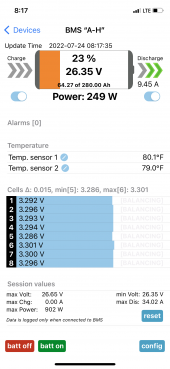
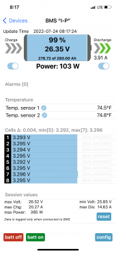
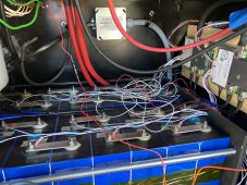
Just fired up my system. I have two 24v 280Ah Eve packs built with Overkill 8s BMS’s attached. So my total system has 16 cells (8s2p) for a 24v 560Ah system. I’m running an MPP Hybrid LV2424.
My question is this…how do the two packs work together? It seems like one was pulling power from the other and I can’t figure out why. Each pack was top balanced, but I did hook up the first pack before the second one, so the two packs are NOT equal. Let me know if I forgot any detail needed.
 

Attachments

  • 366083BD-9C37-479F-BA87-90FA635BD304.png
    366083BD-9C37-479F-BA87-90FA635BD304.png
    578.5 KB · Views: 11
  • 8CE3B5EC-0EE2-4A75-B269-E37AB8CCD0BF.png
    8CE3B5EC-0EE2-4A75-B269-E37AB8CCD0BF.png
    584.8 KB · Views: 11
Each pack was top balanced, but I did hook up the first pack before the second one, so the two packs are NOT equal.

This could be your problem. I installed my two batteries at the same time after top balancing and have seen no issues in two years. I have the same cells and BMS you do but in 4s.

That said, the batteries do not see the exact same amps in/out. The difference is very small. Small enough that I don't worry about it.

The only way I would be able to tell if one battery is pulling from the other would be to turn off the main switch. Even then, my shunt is still online I think.
 
How are they wired? Does the positive connect to one battery and the negative from the other?
If both positive and negative loads (both BMSs are showing discharge) are connected to A-H, that would explain your pics.
No. Both positives go to a bus bar and likewise with the negatives. They are both discharging at the moment. However, yesterday A-H was discharging 14-15v while I-P was charging by the same amount. So I wasn’t sure what the heck was going on.
 
This could be your problem. I installed my two batteries at the same time after top balancing and have seen no issues in two years. I have the same cells and BMS you do but in 4s.
Yeah, I was thinking that. I’m still trying to get the shore and generator wired into the system via the transfer switch. Problem is that I’m leaving for Bible camp in a few hours and will be gone a week. ?
 
No. Both positives go to a bus bar and likewise with the negatives. They are both discharging at the moment. However, yesterday A-H was discharging 14-15v while I-P was charging by the same amount. So I wasn’t sure what the heck was going on.

I would verify all battery and cell voltages with a multimeter at the cell terminals (not the bus bars, studs or ring terminals). Something seems out of kilter.

In theory, parallel batteries would eventually come into balance given sufficient time.
 
I would verify all battery and cell voltages with a multimeter at the cell terminals (not the bus bars, studs or ring terminals). Something seems out of kilter.

In theory, parallel batteries would eventually come into balance given sufficient time.
The voltage will come into balance but the SOC won't until they have been charged into the high knee.
OP if you have a clamp meter lets verify your BMS's shunt.
Check each battery, and then the aggregate.
 
The voltage will come into balance but the SOC won't until they have been charged into the high knee.
OP if you have a clamp meter lets verify your BMS's shunt.
Check each battery, and then the aggregate.
Ok. Let me finish pouring my coffee and then I’ll jump in there.
 
The voltage will come into balance but the SOC won't until they have been charged into the high knee.

I wrote that assuming that charging was present. Two batteries sitting there with no charge and expecting them to balance would be an exercise in futility.
 
A-H = 4.25v
I-P = 2.26
Together = 6.11
Assuming the metric is actually amps...
4.25+2.26=6.51
The difference is may be explained by differences in resistance along the parralel paths

Can you please post a picture of the core busbars were everthing aggregates.
Also pictures of the joinery on the batteries.
 
Assuming the metric is actually amps...
4.25+2.26=6.51
The difference is may be explained by differences in resistance along the parralel paths

Can you please post a picture of the core busbars were everthing aggregates.
Also pictures of the joinery on the batteries.
Oops…hadn’t had my coffee yet. Lol!
It’s still a mess as I have yet to clean it all up until I have everything working. Note the red cable from negative bus bar, that’ll be replaced with a black.
 

Attachments

  • image.jpg
    image.jpg
    200.8 KB · Views: 17
  • image.jpg
    image.jpg
    184.5 KB · Views: 17
  • image.jpg
    image.jpg
    354.5 KB · Views: 17
Oops…hadn’t had my coffee yet. Lol!
It’s still a mess as I have yet to clean it all up until I have everything working. Note the red cable from negative bus bar, that’ll be replaced with a black.
I can't really tell what I'm looking at other than the shunt.
What does the red wire of the busbar that is proximal to the shunt go?

My suggestion is to stress test the system and look for hot spots.
The hot spots are caused by sub-optimal joinery.
I suspect when you address the issues identified you will get more equitable current flow and a more efficient system into the bargain.
 
I'm not a fan of stacking ring terminals/lugs, as seen on the silver box in your second picture. An alternative solution would be to put a lug on each side of the terminal and use a bolt/nut to secure the two lugs. That gives each lug equal access to the load/charge. Plus, you have one lug rotated in such a way that it's not making full contact.

The converter feed in cable needs to be on the other side of your shunt.
 
Back
Top