


You are using an out of date browser. It may not display this or other websites correctly.
You should upgrade or use an alternative browser.
You should upgrade or use an alternative browser.
Very new to solar but started purchasing items, not sure of the final specs of the whole system.
- Thread starter kromc5
- Start date
Trying to find the largest wattage bifacial, not seen these before shingled panels I emailed them for a price quote.
 www.bluesunpv.com
Buy Bluesun new high efficiency shingled bifacial solar panel N-Type Monocrystalline 700 watt solar panels,Professional Bluesun new high efficiency shingled bifacial solar panel N-Type Monocrystalline 700 watt solar panels Manufacturers
Bluesun new high efficiency shingled bifacial solar panel N-Type Monocrystalline 700 watt solar panels and Solar Panel are hot sale now! Large discount at Bluesunpv.com.
www.bluesunpv.com
Last edited:
I saw a thread talking about emps and several devices and so I emailed midnite out of curiosity since I have 10 of them installed.
EMP’s are complicated due to the speed of surge that is experienced. At this time we do not advertise our product for EMP protection however our MNSPD line is listed to the same UL 1449 standard as many of the popular EMP advertised devices on the market. This means that they are required to meet the same functionality standards as those other devices.
Sue Stankevitz
North American Sales Manager
MidNite Solar Inc.
Last edited:
Cleaning up downstairs and noticed a slight bend in my 1500lb rack supports, could not fit my larger level in but it helps show the difference. 1st pic is a rack support on the new rack. Just need a few people to lift these up while I change out the racks. I guess there is no issue since its been standing for sometime now.
Attachments
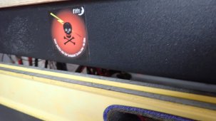
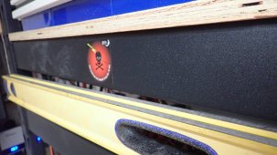
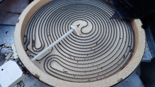
Starting my new Kickstarter soon and only need 1 million dollars to start my ultra efficient direct to pot heating range. We built a prototype robotic controlled hammer system to make these incredible ranges. Low intro price of 4k for the base model. If we hit 100 billion dollars we can price them at 6k.
I was curious to see if there was any significant heat damage, but none I can observe. Really surprised considering how much of the top melted.
I was curious to see if there was any significant heat damage, but none I can observe. Really surprised considering how much of the top melted.
Attachments
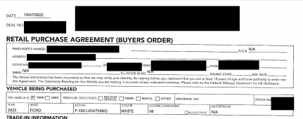
Got my purchase order yesterday in the mail, after editing looks like a real foia request. They had promised no adm and after many months of wafting they did not add any. But can we keep it charged is the question? Current estimate that we can pick it up is near the end of Nov.
Basic charger specs: Can be run on 120v as well.
Connector uses industry standard/universal SAE J1772 connector. Compatible with electric vehicles on the market today (that are compliant with SAE J1772)
• Up to 7.36 kW/30 amp output for SAE
• Dynamic color LED lights show power and
charging status
• Usage: Capable for both indoor and outdoor use.
IP-66 rated when connected
• Lightweight cable; length is 20 ft.
• Input Voltage: 120V or 230V/240V
• Input Frequency: 50Hz – 60Hz
• Weight: 9.5 lbs.
• In the Mobile Power Cord carrying case:
• Ford Mobile Power Cord
• 20 ft. Cord and Charge Coupler
• Low-Voltage Connector
• High-Voltage Connector
• Wall Bracket
Attachments
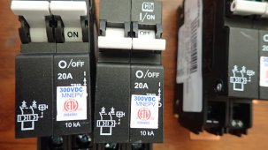
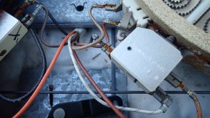
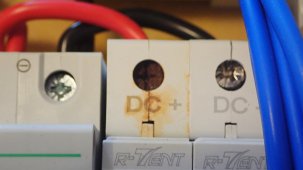
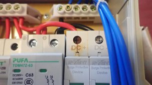
I went out late last night and removed exchanged the ecobox, this was the reason for the midnite breakers. Once in a while I go and just check all the combiners and voltages. I found something odd in the ecobox, I have no idea on what was happening. Any ideas on this?
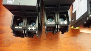
These are doubled enclosed, it appears to have gotten hot, all voltages were fine and the scc amps was unchanged.
These are doubled enclosed, it appears to have gotten hot, all voltages were fine and the scc amps was unchanged.
Attachments
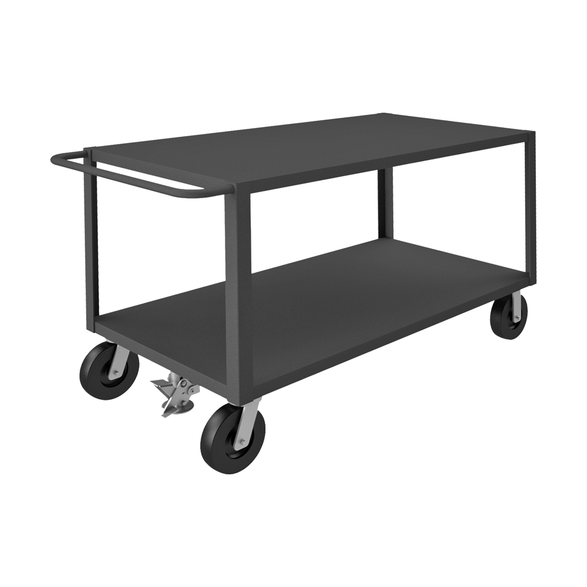
Found a couple of these and will give them a try. Sometime in the future I would like to redo the floor. But if you look up at post 925 you can the supports are slightly bending even though they were 1500lb rated. These are 2500 lbs. per shelf and will lower them substantially as well.
 www.durhammfg.com
Heavy Duty Service Truck, 2 Shelves, 30 x 60, 5000 lbs. Capacity, Floor Lock - Durham Manufacturing
Heavy Duty Service Truck, 2 Shelves, 30 x 60, 5000 lbs. Capacity, Floor Lock
www.durhammfg.com
MrM1
I'm Here, But I'm Not All There
For batteries?Found a couple of these and will give them a try. Sometime in the future I would like to redo the floor. But if you look up at post 925 you can the supports are slightly bending even though they were 1500lb rated. These are 2500 lbs. per shelf and will lower them substantially as well.
Heavy Duty Service Truck, 2 Shelves, 30 x 60, 5000 lbs. Capacity, Floor Lock - Durham Manufacturing
Heavy Duty Service Truck, 2 Shelves, 30 x 60, 5000 lbs. Capacity, Floor Lock
(Still enjoying your journey. I just don't know enough to make intelligent relevant comments)
It is for the batteries, after getting the second rack and setting up I noticed the difference.For batteries?
(Still enjoying your journey. I just don't know enough to make intelligent relevant comments)
Wish I had thought of something like this before that allowed for them to be moved and high weight limit.
But I did not think that the racks would bow like this.

Very new to solar but started purchasing items, not sure of the final specs of the whole system.
Gotten even darker so back to totally negative for the day I suspect.
 diysolarforum.com
Hedges
I See Electromagnetic Fields!
- Joined
- Mar 28, 2020
- Messages
- 20,678
I went out late last night and removed exchanged the ecobox, this was the reason for the midnite breakers. Once in a while I go and just check all the combiners and voltages. I found something odd in the ecobox, I have no idea on what was happening. Any ideas on this?
These are doubled enclosed, it appears to have gotten hot, all voltages were fine and the scc amps was unchanged.
Looks like rust to me. Condensation?
Applied voltage relative to environment might enhance/suppress corrosion.
Unlike your new Midnight/CBI breakers, these aren't two poles daisy-chained but are actually at positive & negative voltages, correct?
The surge protector and breaker "+" terminal are of course at same potential. Maybe screw is of different metal/plating?
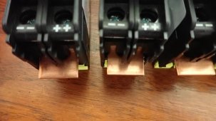
Runs cooler, so doesn't dry as quickly? Although short copper run conducts heat. But there will be a distinct temperature gradient, maybe breaker self-heats above dew point while surge arrestor does not. Really a "degenerate" case you could have to go out of your way to create.
"doubled enclosed" - sealed or vented? SMA cautions against working on their sealed enclosures under some weather conditions. Don't want to introduce and trap moisture.
Negative screw for surge arrestor is offset. Just manufacturing tolerances, not loose?
It is so tempting to put two wires in one screw terminal, isn't it?
For some reason, not allowed by code. Except when the screw terminal is a splice like a split bolt.
I've found ferrules intended for two wires. Finding UL listed ferrules and crimper (listed together) without breaking the bank is another story.
I haven't seen any reason I can't strip a length of wire in the middle as well as both ends, so I've slipped one through a terminal (similar to your bus bar) and put one end in each of the other components. That accomplishes the multiple connections with only one wire under each screw. So long as terminal is sufficiently large to slip over insulation.
One screw for blue wire looks like it was never tightened at all.

The odd part is I had two in the same box the one beside it was fine. As for the screws I had removed the wires and the surge suppressor wires and brought inside for the photo. This is why that one is loose it was used for the surge negative input.Looks like rust to me. Condensation?
Applied voltage relative to environment might enhance/suppress corrosion.
Unlike your new Midnight/CBI breakers, these aren't two poles daisy-chained but are actually at positive & negative voltages, correct?
The surge protector and breaker "+" terminal are of course at same potential. Maybe screw is of different metal/plating?
Runs cooler, so doesn't dry as quickly? Although short copper run conducts heat. But there will be a distinct temperature gradient, maybe breaker self-heats above dew point while surge arrestor does not. Really a "degenerate" case you could have to go out of your way to create.
"doubled enclosed" - sealed or vented? SMA cautions against working on their sealed enclosures under some weather conditions. Don't want to introduce and trap moisture.
Negative screw for surge arrestor is offset. Just manufacturing tolerances, not loose?
It is so tempting to put two wires in one screw terminal, isn't it?
For some reason, not allowed by code. Except when the screw terminal is a splice like a split bolt.
I've found ferrules intended for two wires. Finding UL listed ferrules and crimper (listed together) without breaking the bank is another story.
I haven't seen any reason I can't strip a length of wire in the middle as well as both ends, so I've slipped one through a terminal (similar to your bus bar) and put one end in each of the other components. That accomplishes the multiple connections with only one wire under each screw. So long as terminal is sufficiently large to slip over insulation.
One screw for blue wire looks like it was never tightened at all.
Hedges
I See Electromagnetic Fields!
- Joined
- Mar 28, 2020
- Messages
- 20,678
You could inspect the wire/terminal contact surfaces. Different material, may not have as bad corrosion.
Since this is surge arrestor it carries zero current except during an event, so wouldn't notice voltage drop any other time, or heating ever.
Sealed box? Let dry out under hot conditions, seal with packet of "do not eat" desiccant?
But it really seems like water got just on that one part. Or salt from assembler's sweat?
It's very odd how badly and quickly it corroded, did not seem to cause any issues but decided to replace it.You could inspect the wire/terminal contact surfaces. Different material, may not have as bad corrosion.
Since this is surge arrestor it carries zero current except during an event, so wouldn't notice voltage drop any other time, or heating ever.
Sealed box? Let dry out under hot conditions, seal with packet of "do not eat" desiccant?
But it really seems like water got just on that one part. Or salt from assembler's sweat?
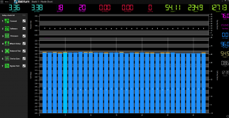
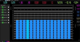
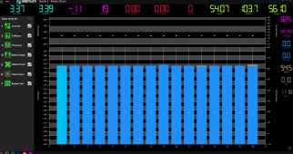
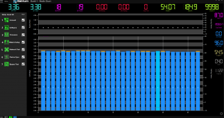
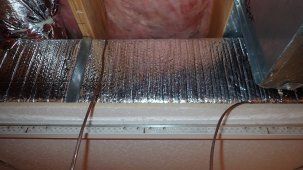
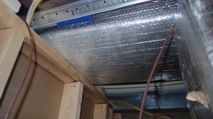
We had not really used the heat side since installing the mrcool diy 3ton, I verified it started but test it long term.
It started the last week since using it, sometimes it would start up and run just fine or it would startup but stop warming and keep running.
Other times it would not even recognize the call from the ecobee and only the blower would run.
What I learned, rc1 / c on the heat pump when the heat call is made should read 25v. This voltage would show and drop back down to 13volts.
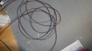
I tried one of the spare lines in the wall and voltage was not steady but still acting up. WG1 also makes the call for heat but the cable going from the blower to the heat pump was also intermittent. Lowes only had 250ft 18/8 in stock and had to redo both hvac communications lines and now everything is working. Crazy all the ac lines were fine but both cables from the thermostat and the one from the blower were causing issues for the heat.
It started the last week since using it, sometimes it would start up and run just fine or it would startup but stop warming and keep running.
Other times it would not even recognize the call from the ecobee and only the blower would run.
What I learned, rc1 / c on the heat pump when the heat call is made should read 25v. This voltage would show and drop back down to 13volts.
I tried one of the spare lines in the wall and voltage was not steady but still acting up. WG1 also makes the call for heat but the cable going from the blower to the heat pump was also intermittent. Lowes only had 250ft 18/8 in stock and had to redo both hvac communications lines and now everything is working. Crazy all the ac lines were fine but both cables from the thermostat and the one from the blower were causing issues for the heat.
Attachments
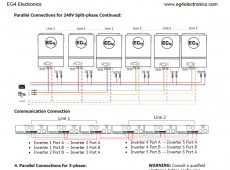
I have been working to add another load panel but have not determined how to do so. I'm thinking that the only option to add more power is to go with eg4 6500w. It hit me that since I replacing the racks that hold the batteries if frees up much needed space. I can easily leave everything as it its and just add these. If anything should happed I would have really to much redundancy but that is good. I have been reading through the manual and even called but was unsure about them. I'm guessing with each one added it doubles everything including max loads / surge etc. 12kw is really not enough one you start adding garage ev etc. I can actually fit 6 but thinking 4 would be sufficient.
Attachments
Last edited:
MrM1
I'm Here, But I'm Not All There
Yeah I guess your only option with the 12kw would be to 2 totally stand alone systems from the batteries through to the AC loads
That's actually our load plan here as the farm grows
That's actually our load plan here as the farm grows
Similar threads
- Replies
- 52
- Views
- 4K