diy solar

diy solar

Xuba Electronics: DEAL - 280AH LiFePo4 cells. Purchase & Review

Digital callipers will be perfect for getting dimensions - I can add a little wiggle room in my designs. Are you able to provide the dimensions I asked for? I did go back to the previous posts but I was struggling to understand some of the measurements and I think I need additional measurements such as the diameter of the terminals (and if they're the same diameter). These are the dimensions I need:

  1. centres of the terminals in relation to the edges of the cell - need accurate dimensions here, there was an earlier post with rough dimensions which doesn't help when doing 3D designs.
  2. centre-to-centre dimensions of the terminals
  3. diameter of the raised terminals (check to see if they're the same diameter)
#1. 36mm to 37mm side to side 36mm is probably the better one
42.9mm to 43.2mm this one was easier long way edge 42.9mm is better

#2 Real hard to tell because it would short out the cell + to - on a cell
The best guess was measuring the same spot on a bus bar inside edge neg to outside edge pos
87.1mm is the best I got and I'm not comfortable claiming it.

#3 23.8mm to 23.9mm raised part this one I'm pretty sure of

#1 and #2 were guessing where the center of the terminal was. I had a steel rule against the outside for both ways #1
so the variable is getting the center of the terminal

I may try again later or tomorrow

Great, thanks for these mate! They worked out pretty close using your 87mm centre-to-centre distances.

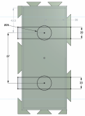
Here's some of the dimensions which I've got

Screen Shot 2020-04-24 at 2.59.54 pm.png
 
I've updated the design to include dovetails/interlinks on all sides. I've done away with doing flat ends because it would mean too many variations of the design at this point. Can do this later if/when I get accurate dimensions.

I still really need accurate dimensions for the following:
  1. centres of the terminals in relation to the edges of the cell - need accurate dimensions here, there was an earlier post with rough dimensions which doesn't help when doing 3D designs.
  2. centre-to-centre dimensions of the terminals
  3. diameter of the raised terminals
I've based the design on 72mm wide, 174mm long. Allowed 0.5mm tolerance for dovetails.

STL's available on thingiverse here: https://www.thingiverse.com/thing:4307945

View attachment 11718

View attachment 11719
Looking very Good. Your cell spacers will be very strong and fit every way the cells can be orientated.
Wonder if you should move this topic to a separate thread? Maybe you could get with Heap64 and add it to his thread, He's done some very nice work with his spacers too.
 
I've updated the design to include dovetails/interlinks on all sides. I've done away with doing flat ends because it would mean too many variations of the design at this point. Can do this later if/when I get accurate dimensions.

I still really need accurate dimensions for the following:
  1. centres of the terminals in relation to the edges of the cell - need accurate dimensions here, there was an earlier post with rough dimensions which doesn't help when doing 3D designs.
  2. centre-to-centre dimensions of the terminals
  3. diameter of the raised terminals
I've based the design on 72mm wide, 174mm long. Allowed 0.5mm tolerance for dovetails.

STL's available on thingiverse here: https://www.thingiverse.com/thing:4307945

View attachment 11718

View attachment 11719
Looks really good BUT you need to keep enough space for busbars which should allow for at least 3.0 cm width, as well take into account the thickness of a busbar & bolt/nut head on top of that and there is no way to know what size busbar or bolt/head nut will be but likely something on the order of 1cm to 1.5cm from the top of the cell post for safe margin.
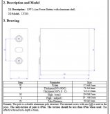
EVE-280AH-Dimensions.JPG
 
Looks really good BUT you need to keep enough space for busbars which should allow for at least 3.0 cm width, as well take into account the thickness of a busbar & bolt/nut head on top of that and there is no way to know what size busbar or bolt/head nut will be but likely something on the order of 1cm to 1.5cm from the top of the cell post for safe margin.
View attachment 11733

Thanks for the dimensional drawing Steve. I'll adjust my design for the centre-to-centre terminal distances.

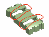
There's plenty of room for busbars and terminal clearances via cutouts - see circled red area in the image below.

Screen Shot 2020-04-24 at 12.54.10 pm.png
 
Thanks for the dimensional drawing Steve. I'll adjust my design for the centre-to-centre terminal distances.

There's plenty of room for busbars and terminal clearances via cutouts - see circled red area in the image below.

View attachment 11734
In my case, I am using 20mm X 5mm 110 Copper Bar Stock for busbars which is effectively double the busbars that Amy sends from Xuba. I don't know what other busbars other companies are supplying for these cells. On another set of packs I used 30mm wide copper bar stock which I also made up to replace the aluminium ones I was supplied with.

I'm not sure how flat the top of your design is over the centre vent hole, there should be enough space to allow for the vent to work, maybe a hole above the vent area would be a prudent mod.

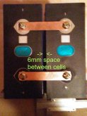
Something to note, the busbars sent by Xuba and I will assume others as well, are only long enough to have the cells snugged up next to each other, when pushed apart as far as possible the space between the cells is 6mm,
cell-spacing.jpg
 
In my case, I am using 20mm X 5mm 110 Copper Bar Stock for busbars which is effectively double the busbars that Amy sends from Xuba. I don't know what other busbars other companies are supplying for these cells. On another set of packs I used 30mm wide copper bar stock which I also made up to replace the aluminium ones I was supplied with.

I'm not sure how flat the top of your design is over the centre vent hole, there should be enough space to allow for the vent to work, maybe a hole above the vent area would be a prudent mod.

Something to note, the busbars sent by Xuba and I will assume others as well, are only long enough to have the cells snugged up next to each other, when pushed apart as far as possible the space between the cells is 6mm,

Great point regarding the vent hole - I've added it into the design. You don't happen to have the dimensions of this do you? Length to the ends of each arc and width would be great!

Not sure what to do about the busbars, it's possible that the sellers might be able to provide longer ones? Otherwise custom busbars will be necessary.
 
For those of you still in the market for one of these, I got an order in with Amy for 4 280ah cells for $550 including rail shipping to the EU (no customs/duties this way).

What BMS and MPPT are you guys running with these? Thanks.
 
For those of you still in the market for one of these, I got an order in with Amy for 4 280ah cells for $550 including rail shipping to the EU (no customs/duties this way).

What BMS and MPPT are you guys running with these? Thanks.

I have paid $970 /€920 for 8 cells, with shipment, and tax and customs included. Delivery to the door.

Got a video with the volts and resistance of each cell. They vary between 0.15 - 0.19 Ohm.
Voltages are all exact 3.32. Should i be pleased with these numbers?
 
Amy is saying they will have metal battery boxes large enough for 8 cells very soon. I'm holding off doing anything more with my 3d printed supports until I see what they come up with. If these look good I will design 3d print parts to support the cells and hopefully a Chargery BMS in any space remaining in the box.
 
Amy is saying they will have metal battery boxes large enough for 8 cells very soon. I'm holding off doing anything more with my 3d printed supports until I see what they come up with. If these look good I will design 3d print parts to support the cells and hopefully a Chargery BMS in any space remaining in the box.

Thanks, I'd love one for my 4 cell battery. I'll ask her about those.
 
There are pics, I think in this thread, where someone stuck a 4 cell build in a group 31 plastic battery box and it fit fine.

Thanks! I had to look that up. I’m in the EU and I don’t think we have that brand here but I’ll look up similar boxes online.
 
Thanks! I had to look that up. I’m in the EU and I don’t think we have that brand here but I’ll look up similar boxes online.
Group 31 is just a standard size of a battery. I don't know what Y'all use for references for battery sizes over there. I know back in the 70s/80s MB used some real big batteries in their cars, that might have been around the same size.
That size is used a lot in big rig trucks and marine use.
 
Thanks! I had to look that up. I’m in the EU and I don’t think we have that brand here but I’ll look up similar boxes online.
I've been trying to find a cross reference chart for American to European battery sizes, but not having much luck.
What are the common Marine/Boat deep cycle batteries over there?
Another place is compare the size to surplus metal Military ammo cans. Maybe you'll get lucky and one will match up to the size you need.
 
Another real-world-like capacity test. A more desirable result this time.

8 Xuba 3.2V 280Ah cells (24V nominal) - Rated capacity 7,168Wh

Test Range
Upper limit: 27.15V (rested voltage)

Lower limit (under low C-rate load):
25.50V, 5,749Wh = 80% usable capacity
24.90V, 6,165Wh = 86% usable capacity
24.83V, 6,660Wh = 93% usable capacity
23.00V, 6,893Wh = 96% usable capacity

1st Pic - Test begins about 7:30am - Inverter off, rested 27.15V, reasonably balanced cells, zero'd Drok meter (right)
1.jpg

2nd Pic - Inverter powered on (left), uses about 40W on its own (no other loads), minor voltage drop
2.jpg

3rd Pic - I powered a bunch of stuff on - Coffee maker, refrigerator, desktop computer & monitors, stereo, osculating fan, TV & sound bar, laptop w/ docking station & monitors; All variously powered on & off throughout the day (also used the microwave for lunch & dinner).

Notice the voltage dropped from over 27V to less than 25V when the battery was mostly full. Over a 2V drop when putting a sizable load on the battery (1,830W or .25C rate). Something to keep in mind when setting the low-voltage alarm and low-voltage cut-off settings. When the battery capacity gets low and you're still wanting to use things like a microwave, toaster oven, coffee maker, window Air-conditioner, etc...., you may need to compensate using lower settings.
4.jpg

4th Pic - Reached 80% usable capacity at 25.5V under load
5.jpg

5th Pic - Reached 86% usable capacity at 24.9V under load
8.jpg

6th Pic - Reached over 92% at 24.87V under load
9.jpg

7th Pic - Inverter low-voltage alarm went off, I'd set it to 23.10V, battery went to just below 23V. I powered everything off. About 96% usable capacity. Test effectively ends about 10:30pm

Notice the voltage dropped from 24.87V to 22.95V in less than 30 minutes time with less than .1C discharge rate (<717W).
The lower limit dropped off quickly once below 24.8V.
11.jpg

8th Pic - Inverter is still on (no other loads). Notice the voltage bounces back to 23.5V after just a few minutes.
12.jpg

9th Pic - Inverter powered off, no load, voltage slowly leveling off
13.jpg

10th pic - 7:30am next morning, battery rested the whole night. Resting voltage leveled off at 24.2V.
So, from lower limit 23V under load to rested 24.2V in several hours time. Over a 1V rebound. Something to be aware of when using voltage as a general measure of the battery.
15.jpg

Yeah, but what does all this mean???
It appears the Xuba 280V LiFePO4 cells are working as expected (advertised), at least from my experience so far. After a number of various capacity tests and a learning-curve on my part, the cells seem to be working well for off-grid solar power usage (low C-rates).

One thing I'm not sure about is high C-rates. I haven't really tried rates much above .25C (<2kW). Mainly, because what I've been testing with is a power system temporarily put together, using 1 AWG cable with uncrimped lugs, stock bus bars, and a couple of 50ft extension cords and power strips. The seemingly significant voltage drop under higher loads could be because of my improvised setup (not very efficient).

For me, it looks like the cells are going to work for what I have planned (ie. hurricane season backup power & general DIY hobby use). I was aiming for 10kW potential usable power.

16 Xuba 3.2V 280Ah cells (24V nominal) - Rated capacity 14,336Wh

Rough (ball park) estimates:
14kW x 85% = 12kW Battery charged to about 85% capacity (range somewhere between 27.2V - 24V)
12kW x 85% = 10kW Efficiency & Inverter DC to AC conversion losses (average about 15% loss)

I think a reasonable balance between available usable power and good battery longevity.

Thanks Sgt Raven and Steve_S for the backup suggestions when making long posts. I did both, used a text editor and the disk icon (Save draft) feature. Didn't need them this time, but good peace-of-mind, though.
 
Last edited:
Another real-world-like capacity test. A more desirable result this time.

8 Xuba 3.2V 280Ah cells (24V nominal) - Rated capacity 7,168Wh

Test Range
Upper limit: 27.15V (rested voltage)

Lower limit (under low C-rate load):
25.50V, 5,749Wh = 80% usable capacity
24.90V, 6,165Wh = 86% usable capacity
24.83V, 6,660Wh = 93% usable capacity
23.00V, 6,893Wh = 96% usable capacity

.... big snip.......


16 Xuba 3.2V 280Ah cells (24V nominal) - Rated capacity 14,336Wh

Rough (ball park) estimates:
14kW x 85% = 12kW Battery charged to about 85% capacity (range somewhere between 27.2V - 24V)
12kW x 85% = 10kW Efficiency & Inverter DC to AC conversion losses (average about 15% loss)

I think a reasonable balance between available usable power and good battery longevity.

Thanks Sgt Raven and Steve_S for the backup suggestions when making long posts. I did both, used a text editor and the disk icon (Save draft) feature. Didn't need them this time, but good peace-of-mind, though.

On my long slow test. Starting at 13.9V, it dropped to 13.5V in a hour and 13.4V the 2nd hour.
Then it leveled off at 13.4V for days and then slowly dropped to 13.1V
I stopped the test at 12.8V because my fridge gave a E1 error code, voltage too low to start compressor.
I didn't think to reset the voltage limits lower on the fridge controls .

According to my Smart BMS, I had 308AH for the first cycle. Which works out to +10% over the AH rating. From all I've read, that's pretty common on a new build.

Still the battery ran my fridge/freezer, charged my phone, tablet, and a power bank I used with them for 6.5 days.
Charging it back up at 35A-20A it took about 12 hours.

On backing up a post, I'm sure most of us has spent some time typing something out, just for it to go Poof.
I know a few times my wife would come home all pissed off, lost a whole days of work when the computer crashed at the end of the day, just when she was going to save it, too..
 
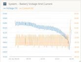
Just did a quick and dirty test and results look good; top balanced at 3.62v and let a portable construction heater battle an air conditioner with the Victron Multiplus inverter set to shut down at 48v. Hence the cyclic load. Recorded 13.88kwh / 265.3 AH through a Victron BMV-712. Pack was at 49.1v after a 5 min rest and cells varied from 2.94 to 3.17. Will charge it back up at 32A and see if it's still balanced at the top, and then do a slower discharge test that's more in line with what I will be using the battery for.

Did a 200 watt discharge the yesterday hence the low starting voltage in the chart, and starting charge back up in the end

dischargetest.png.
dischargetest2.png
 
Another real-world-like capacity test. A more desirable result this time.

8 Xuba 3.2V 280Ah cells (24V nominal) - Rated capacity 7,168Wh

Test Range
Upper limit: 27.15V (rested voltage)

Lower limit (under low C-rate load):
25.50V, 5,749Wh = 80% usable capacity
24.90V, 6,165Wh = 86% usable capacity
24.83V, 6,660Wh = 93% usable capacity
23.00V, 6,893Wh = 96% usable capacity

Yeah, but what does all this mean???
It appears the Xuba 280V LiFePO4 cells are working as expected (advertised), at least from my experience so far. After a number of various capacity tests and a learning-curve on my part, the cells seem to be working well for off-grid solar power usage (low C-rates).

One thing I'm not sure about is high C-rates. I haven't really tried rates much above .25C (<2kW). Mainly, because what I've been testing with is a power system temporarily put together, using 1 AWG cable with uncrimped lugs, stock bus bars, and a couple of 50ft extension cords and power strips. The seemingly significant voltage drop under higher loads could be because of my improvised setup (not very efficient).

For me, it looks like the cells are going to work for what I have planned (ie. hurricane season backup power & general DIY hobby use). I was aiming for 10kW potential usable power.

16 Xuba 3.2V 280Ah cells (24V nominal) - Rated capacity 14,336Wh

Rough (ball park) estimates:
14kW x 85% = 12kW Battery charged to about 85% capacity (range somewhere between 27.2V - 24V)
12kW x 85% = 10kW Efficiency & Inverter DC to AC conversion losses (average about 15% loss)

I think a reasonable balance between available usable power and good battery longevity.

Thanks Sgt Raven and Steve_S for the backup suggestions when making long posts. I did both, used a text editor and the disk icon (Save draft) feature. Didn't need them this time, but good peace-of-mind, though.

Thanks for doing these tests. I think if you were to charge and discharge these cells to the specified voltage limits that you'd achieve the advertised capacity.

What I find interesting is that these cells are supposed to be the same as all the other 280Ah cells advertised on Alibaba (https://diysolarforum.com/threads/x...cells-purchase-review.3850/page-33#post-66256) but for some reason, Xuba's listing lists their upper voltage limit to 3.65V, whereas the other sellers advertise 4.2V. Some (including Xuba) seem to list the low cut-off voltage at 2.5V and some as high as 2.7V.

I appreciate that longevity of the cell will be improved by reducing voltage ranges but the manufacturer should be listing the cell's actual maximum and minimum voltage values then allow the customer to decide if they want more capacity with reduced cycles or reduced capacity with more cycles.
Lithium Ion like the 18650 in my Vape Mods top out at 4.2V These LFP cells should be cut off at 3.65V. You don't gain any useful power above that. The only reason to charge to 3.60V is they will settle down to a lower voltage, once they rest. I'm perfectly fine with stopping at 3.5V. Even there I only gain an extra couple of hours at a slow drain. When you start using them, they will hang out at 3.35V(13.4V) for a long time.
 
Back
Top