diy solar

diy solar

Auto Transformer based all-in-ones (how do they handle ground?)

bgflyguy

New Member
Joined
Jul 8, 2020
Messages
196
All this discussion around the "European" Growatt 5000es has me wondering. What all-in-ones have the same design, but put everything in one box? Will mentions the LV6048 in his latest video, which appears to be two MPPs in a trench coat, but the LVX6048 uses an auto transformer like other LFI inverters. Just like the Growatt 6000t mvp. These are designed for the US, but do they really address the problems everyone is concerned about with the 5000es? Also, many transformerless inverters, aren't really transformerless, they just use high frequency(thus the description) transformers.

I think the whole EU vs. US design thing is misleading. Most of these are made in China and unless they are UL listed, they may or may not be "designed for the us" in reality. Even if they are split phase 240v.

I also think it's pretty stupid that I'm "not allowed" to have 240v appliances like kettles. Do you US guys know how fast they can boil water over there?

So chime in if you have an all-in-one with a schematic for ground/neutral behavior. Victron is great about this stuff, how about others?

I own both the 5000es and the 6000t, but they are in boxes. I didn't buy the 5000es from SS, and I have no need for an autotransformer, but I'm still following along to the drama.
 
The primary problem with using the EU models in North America is that in Europe, the neutral is one of the legs of the 240V, and in North America, neither leg of the 240V is neutral. If the EU model does a neutral-ground bond, one of the legs of the 240V gets tied to the ground....and that can cause all sorts of problems in the US where neutral is designated differently.

These are designed for the US, but do they really address the problems everyone is concerned about with the 5000es?

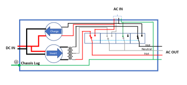
I do not have one of the inverters you are talking about, but I understand the problems with grounding well enough that I am very confident a low-frequency inverter can easily be made that does not have the problem. (however, it might use an isolation transformer instead of an auto transformer) The Low-frequency Split phase that @Will Prowse opened up in his video had a single transformer, so I am assuming it is not two 120V low-frequency inverters that are 'glued together'. I don't know the exact design, but something like this would work:

Edit: Corrected charger inputs in both diagrams.

1643091957224.png

I think the whole EU vs. US design thing is misleading. Most of these are made in China and unless they are UL listed, they may or may not be "designed for the us" in reality. Even if they are split phase 240v.
Almost by definition, if the inverter has split-phase input or output, it is designed for North America. Yes, whether they did it properly can be a valid question.... but it is designed for North America nonetheless. The higher-end companies will spend the money and do it right.... the 'value' targeted companies may not always get it right. Us DIYers tend to be 'value oriented' so we tend to play in the danger zone.

All companies that sell electrical/electronic 'stuff' successfully deal with this in their products. The trick is finding ways to isolate the various differences to a small part of the design. The advent of the switching power supply made this almost trivial for everything that does not have a large motor or a heating element, but there are still a lot of things that must be different between the markets because of the different standards on the power grid. The inverter is kinda a special case because it operates right in the space where the differences between the grid are....but even then there can be designs that are 95% the same between the NA and Rest-Of-World markets. Using the design I show above as an example, you could change the wiring on the bonding and transfer relay, and it would work for Rest-Of-World

1643091855519.png

I also think it's pretty stupid that I'm "not allowed" to have 240v appliances like kettles.
You are allowed to wire 240 volt sockets and have 240v appliances. It is just not normal to have 240V small appliances. I see nothing that would prevent you from putting a US 240V plug on a European tea kettle.

Speaking of tea kettles... I have used 240V kettles in England and 120V kettles here in the US. I never paid any attention, but I never noticed one being particularly faster than the other. Granted, to be the same wattage, the US kettle would draw twice the current, but that is true for pretty much all types of appliances. (I have noticed that household breakers in the US tend to have larger trip ratings than in Europe).

Of course, this gets us into the age-old debate of 'which is better?' I personally think the EU model is simpler, cheaper, and safer..... but thinking NA is ever going to change ranks right up there with thinking England will start driving on the right side of the road.
 
Last edited:
If you think 120V used in the US is bad, high tech Japan uses 100V and depends on which part of Japan you are in it can be 50Hz or 60Hz, and I doubt that kettle in Japan withe same Wattage will boil slower than in the US or Euro, Watt is Watt no matter where you are at.
 
The models you are seeing don’t use auto transformers but if they did any engineer worth his salt would build in safety designs that eliminate the issues with the Growatt.
First thing would be neutral current monitoring. If it gets too high they would shutdown the inverter.
Second issue would be temperature sensing of the transformer. If it gets to hot they would shutdown the inverter.
Ground and neutral would be handled by relays and lastly it would monitor each phase voltage and once again cut power if a phase went to high.
 
The lvx-6048 is low frequency and according to watt247 includes an auto transformer. I didn't see any real details about the lv-6048 though, it still looks like two MPPs in a trench coat to me.

Thanks for the input FilterGuy. I really appreciate your effort towards documentation and sharing knowledge. There was a thread on the lv6048 where I know you spent considerable effort to track down and outline a safe way to wire ground/nuetral as well as the resources here:


I guess part of my frustration is it takes something like that document + the manual to actually understand how these units work, with or without an external Auto-Transformer. And even still we don't know about failure modes. Testing idle units isn't enough to know if there is a dynamic NG bond or how they will behave in all situations. I have 5 inverters, and they all gave a vague guidance and said consult an "expert" None of them had a diagram like what you posted.

I think part of the nature of DIY is understanding all of the pieces and controlling how they work for your specific needs. How do these units become inherently safer by moving the auto transformer inside the same box? All of the units are incredible dangerous if they are hooked up "wrong"


I would also prefer single phase 240v for residential. I don't see a need for two legs in a house. I've seen some regulations against having split phase outlets in places like on counters, but I don't recall and maybe it was something local or made up.
 
As I was creating this thread Copec posted this:

I don't know if anybody else said this, but pretty much every inexpensive low-frequency inverter that produces split phase power (ie direct from China), suffers the same problems as using an EU inverter with the neutral<->ground bond removed. I have a Growatt 12000t low frequency inverter, and I've seen its internal auto-transformer balancing grid currents when in bypass mode (although the most I've ever seen was ~5A when there was a >3V difference between L1/L2 during the summer with all the neighborhood AC), the difference is that the auto-transformer L1/L2 breaker is the breaker to the inverter too.

So imho, the question is still valid, and until it shows up in FilterGuy's doc we probably can't trust it. Even if it is "designed for US"
 
One thing this discusion points out is that US version of the same model number may be different than rest-of-world. I need to think about how I deal with this in my document....
 
The lvx-6048 is low frequency and according to watt247 includes an auto transformer.
No it is a fully isolated transformer, input is around 55v AC as derived from the battery and driven by the MOSFETS.
Secondary is 120-0-120.

In theory, even the high frequency inverters are fully isolated as they have an output transformer too that fully isolates between the switched saw/square/sine input voltage and the secondary 120 or 240v that is a ragged sine wave.
That's great to hear. Where did you get this from? I didnt see it in my efforts, but this is what we need to know.
 
That's great to hear. Where did you get this from? I didnt see it in my efforts, but this is what we need to know.

Some cheap portable high-frequency inverters aren't isolated, deliver +/-60V (relative to battery) so offer 120V between L1 and (non-grounded) N.

Most high frequency inverters would use an isolated high-frequency transformer to create a high-voltage rail of at least 170V (for single phase 120V) or 340V (for split-phase 120/240V or single-phase 240V).

An inverter with 120-0-120 a.k.a. 120/240V split-phase from output of a center-tapped transformer, even if it is an isolation transformer, still has a secondary which will operate as an auto-transformer and attempt to balance the utility line.

"although the most I've ever seen was ~5A when there was a >3V difference between L1/L2 during the summer"

All depends on how much imbalance. More voltage, more current. In the worst case, imagine if the utility transformer lost L1 (or N). Then your balancing transformer would attempt to balance the neighborhood. Light enough loads, might be successful for a while.

If one had an auto-transformer with windings able to carry 40A at 240V, let's say with 50A breaker on L1/L2 and connected by 8 awg. If you connect a 10 kVA load (80A at 120V), each winding will carry 40A, so neither L1 nor L2 leg trips the breaker. But N will carry 80A, the grid will supply 40A on L1 to the load, and autotransformer supplies another 40A on L1 to the load.

That would be 80A the neutral wire can't handle. Either need a 3rd breaker pole on neutral, or neutral wire needs to be heavy enough to carry the current of L1 + L2 breaker poles. A thermal disconnect would be nice to protect the transformer, but it is neutral wire I'm worried about now.
 
An inverter with 120-0-120 a.k.a. 120/240V split-phase from output of a center-tapped transformer, even if it is an isolation transformer, still has a secondary which will operate as an auto-transformer and attempt to balance the utility line.
Presumably, they isolate the transformer output when they go into transfer mode. Otherwise, you are correct it could be a big problem

1643644450063.png
Looking at the above diagram it occurs to me that they might not have to isolate neutral if the weren't also creating an N-G bond, but certainly would need to isolate the two hots.
 
Presumably, they isolate the transformer output when they go into transfer mode. Otherwise, you are correct it could be a big problem

View attachment 82020
Looking at the above diagram it occurs to me that they might not have to isolate neutral if the weren't also creating an N-G bond, but certainly would need to isolate the two hots.

If it is a utility-interactive inverter which can backfeed power PV --> battery DC --> AC --> grid, it needs to connect inverter to grid.
In the case of a high-frequency inverter with auto-transformer to establish neutral (Victron, Sunny Boy Storage), on-grid operation can be supported by disconnecting auto-transformer (L1 & L2, or N, or L1 & L2 & N)
In the case of low-frequency inverter, transformer secondary needs L1 and L2 to remain connected to grid in order to feed, so isolating center tap would solve the issue.

Separate inverters from 48VDC to 120VAC, each with its own transformer, is another approach (Sunny Island, Outback, any other 120V inverter that can stack for split phase and/or 3-phase)


Oh by the way, "Charge" path is often through same transformer or high frequency switching circuit.
I was referring to 'inverter charger' or hybred inverters, but yes, Grid interactive does certainly complicate things. I would need to think about it more, but it seems like the inverter could sense when it gets into 'problem territory' and isolate accordingly.

Maybe I am being naive, but it seems like the more reputable companies would understand the problem set and design proper mechanisms to prevent them from being an issue. I would also think that UL would test for these types of issues. (These types of checks and controls are not reasonably possible when trying to combine an independent auto transformer with a 240V inverter)

Having said that..... when we use inverters from companies like Growatt that don't even have UL listing, we are certainly taking chances.
 
An inverter/charger that acts like a UPS, transfer switch for load between grid and inverter, could simply be disconnected. Then it needs separate charge path.
Instead of DPDT relay (transfer switch), many products seem to have DPST, so inverter output might always be on AC output. It can then double as a charger. Some will synchronize to grid and provide support without export, some will not.

Yes, I think the reputable and experienced companies try to get this right, and mostly do. Sometimes bleep happens, then they have to fix it. The 120/240V split-phase winding (whether isolation or auto-transformer) may in fact be OK paralleled with the grid, if it doesn't draw excessive current when within voltage limits. The inverter can disconnect from grid if voltages out of spec. What's interesting is my understanding that it can drive neutral current 2x either line current. Which of course it does, that's its job. The transformer windings can handle that just fine, but the leads coming out (if 3 leads, not four because the windings are series connected externally) have to handle that 2x on the neutral, as does the external neutral connection. Ever see a breaker requirement that is 1/2 what neutral wire awg is provided/specified? That could be 25A breaker and 8 awg neutral.

I think this GroWatt ATS/auto-transformer has a 3-pole breaker which will trip if neutral current is excessive.
Spec says 42A/48A and wire as small as 10 awg on output, which I think is too small. But up to 6 awg fits.

 
Filter Guy has it right for the LV6048. Neutral is switched. Therefore the inverter is isolated in bypass mode. One could use a transfer switch before the AC input on a 5000ES and auto transformer and accomplish the same thing, it just wouldn't charge the batteries off grid because there wouldn't be any power coming in. The LV6048 is designed to charge the batteries in bypass mode so that eliminates that problem.
 
The primary problem with using the EU models in North America is that in Europe, the neutral is one of the legs of the 240V, and in North America, neither leg of the 240V is neutral. If the EU model does a neutral-ground bond, one of the legs of the 240V gets tied to the ground....and that can cause all sorts of problems in the US where neutral is designated differently.


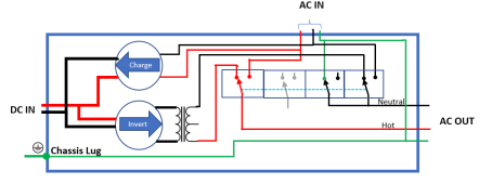
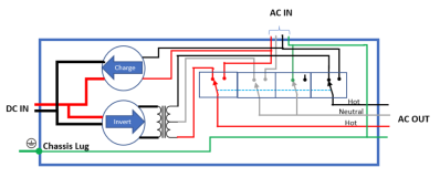
I do not have one of the inverters you are talking about, but I understand the problems with grounding well enough that I am very confident a low-frequency inverter can easily be made that does not have the problem. (however, it might use an isolation transformer instead of an auto transformer) The Low-frequency Split phase that @Will Prowse opened up in his video had a single transformer, so I am assuming it is not two 120V low-frequency inverters that are 'glued together'. I don't know the exact design, but something like this would work:

Edit: Corrected charger inputs in both diagrams.

View attachment 81162


Almost by definition, if the inverter has split-phase input or output, it is designed for North America. Yes, whether they did it properly can be a valid question.... but it is designed for North America nonetheless. The higher-end companies will spend the money and do it right.... the 'value' targeted companies may not always get it right. Us DIYers tend to be 'value oriented' so we tend to play in the danger zone.

All companies that sell electrical/electronic 'stuff' successfully deal with this in their products. The trick is finding ways to isolate the various differences to a small part of the design. The advent of the switching power supply made this almost trivial for everything that does not have a large motor or a heating element, but there are still a lot of things that must be different between the markets because of the different standards on the power grid. The inverter is kinda a special case because it operates right in the space where the differences between the grid are....but even then there can be designs that are 95% the same between the NA and Rest-Of-World markets. Using the design I show above as an example, you could change the wiring on the bonding and transfer relay, and it would work for Rest-Of-World

View attachment 81161


You are allowed to wire 240 volt sockets and have 240v appliances. It is just not normal to have 240V small appliances. I see nothing that would prevent you from putting a US 240V plug on a European tea kettle.

Speaking of tea kettles... I have used 240V kettles in England and 120V kettles here in the US. I never paid any attention, but I never noticed one being particularly faster than the other. Granted, to be the same wattage, the US kettle would draw twice the current, but that is true for pretty much all types of appliances. (I have noticed that household breakers in the US tend to have larger trip ratings than in Europe).

Of course, this gets us into the age-old debate of 'which is better?' I personally think the EU model is simpler, cheaper, and safer..... but thinking NA is ever going to change ranks right up there with thinking England will start driving on the right side of the road.
This is a helpful diagram to explain how low-frequency inverters handle to issue, but this design only inverts power out the AC output port and only consume power through the AC input port.

Zero-export hybrids such as the Conext XW Pro support power output through the AC input as well, and I’d be interested in your thoughts as to how those might be designed.

The Victron Multiplus II only inverts at 120V, but they provide a clear diagram so you can understand how they switch between being able to invert 120VAC out the AC input port while also being able to feed-through 240VAC from the grid to the AC output port or switch to a backup mode where the inverter disconnects from the grid (including mains neutral) and supplies 120VAC to both legs of the AC output (with an isolated backup neutral formed by bonding backup neutral to chassis ground through an additional transfer switch: https://www.victronenergy.com/upload/documents/Datasheet-MultiPlus-II-3kVA-2x120V-EN.pdf

If only all hybrid inverter manufacturers would provide documentation that was this clear…
 
Last edited:
Zero-export hybrids such as the Conext XT support power output through the AC input as well, and I’d be interested in your thoughts as to how those might be designed.
I can't find anything about a Conect XT.... is that the correct name?

I am not a fan of zero export devices because they can not do back-up in the event of grid power failure (At least that is my understanding). Consequently, I have never done a deep dive on zero-export hybrids but... As far as I know, they all only have one AC connection. That one connection will take in energy to charge batteries or it will output energy from solar or batteries. My understanding is that they do the zero export by measuring the current at the service entrance and back off on supplying power before the current starts flowing back to the grid.

If these were implemented with an autotransformer or a center-tapped isolation transformer, they would be subject to the problems of trying to balance Line 1 and Line 2 for the whole grid. I have not thought a lot about how they could avoid the problem, but at a minimum, they would want sensors to make sure the problem does not get out of hand. A couple of possibilities come to mind:
1) Current and/or voltage sensors on the transformer to detect excessive current on the secondary.
2) Temperature sensors to detect problems.
 
I can't find anything about a Conect XT.... is that the correct name?
Sorry, I meant XW Pro: https://solar.schneider-electric.com/product/xw-pro-na-solar-hybrid-inverter/

(Fixed my earlier post to try to minimize the confusion I’ve caused).
I am not a fan of zero export devices because they can not do back-up in the event of grid power failure (At least that is my understanding).
I may be using the term zero-export too loosely.

A classical hybrid inverter that only pushes power out of the AC output is not what I am referring to.

There is another class of hybrid inverter including the Conext XW Pro as well as all of the Solark’s which is able to also push power out into the AC input to offset kin-critical loads consumption. This capability is typically governed / controlled to avoid export to grid by using either CT sensors o an energy meter on the L1 & L2 wires from grid.

This capability is often called ‘zero-export-to-CT-sensor’ and that is the class if inverters I was attempting to refer to when I wrote ‘zero export inverters’.

So my earlier question can be restated by replacing ‘zero export inverters’ with ‘inverters supporting zero export to CT sensor capability’ unless these is a better term to use…
Consequently, I have never done a deep dive on zero-export hybrids but... As far as I know, they all only have one AC connection. That one connection will take in energy to charge batteries or it will output energy from solar or batteries. My understanding is that they do the zero export by measuring the current at the service entrance and back off on supplying power before the current starts flowing back to the grid.
All of that is correct except that many/most of those inverters include both an AC Input/Output for non-critical loads as well as an AC output for critical loads (often called ‘EPS’.
If these were implemented with an autotransformer or a center-tapped isolation transformer, they would be subject to the problems of trying to balance Line 1 and Line 2 for the whole grid.
If the Autotransformer is connected to L1, L2 and N when not in Critical Loads / Emergency Power Supply mode, I agree.

Victron solved this issue by disconnecting L1, L2 and N from AC input and then forming a new isolated Critical Loads Neutral by using a relay to bond Critical Loads Neutral to ground when in EPS mode…

I have not thought a lot about how they could avoid the problem, but at a minimum, they would want sensors to make sure the problem does not get out of hand. A couple of possibilities come to mind:
1) Current and/or voltage sensors on the transformer to detect excessive current on the secondary.
2) Temperature sensors to detect problems.
If a low-frequency inverter is only a true split-phase inverter when in EPS mode and a single-phase 240VAC inverter when grid-tied, there should be no issue because the Autotransformer is only connected when the grid is not.

The only problem with that configuration is that it is not a true ‘zero export’ solution because when grid-tied, there will typically be some export on one leg offsetting an equal amount of consumption on the other.

Solark, I believe, uses 2 high-frequency 120VAC inverters so they can deliver true zero export capability where you x port to either leg is avoided.

I’m curious how a low-frequency inverter such as the Conext XW Pro can deliver the same capability and suppose it is not possible (at least unless they are also causing the rebalancing current from grid issue we are trying to avoid by having the Autotransformer connected in parallel with the transformer on the utility pole)…
 
I am not seeing anything in the documentation that would indicate it is a zero-export inverter like you described.... Could you point me to something that describes that function?

I just looked up the solar and you are correct, it has a loads output as well as a bidirectional grid connection that can be set up with zero export. (I had not realized they had that capability. I certainly don't know their internal structure so I will have to ponder a bit about how they might do it.

Do you happen to know if the solar is a low frequency or high frequency inverter? (I suspect it is a high frequency).
 
Back
Top