diy solar

diy solar

Auto Transformer based all-in-ones (how do they handle ground?)

By the way, another question on this same topic:

Solis has been selling a 240VAC inverter with a companion Autotransformer in the US for years:

https://www.renvu.com/Solis-5kW-Sin...rage-Hybrid-Inverter-with-SunSpec-Transmitter


There is a manual transfer switch integrated into their Autotransformer to enable the inverter to be bypassed powering critical loads so that the inverter can be serviced without interrupting power to critical loads, but the Autotransformer itself seems to always be wired to L1 and L2 under normal operation, exactly as we’ve been concerned crème’s about here.

There is no neutral connection of any kind on the inverter itself while the Autotransformer has both a Neutral in from grid as well as a neutral out to critical loads.

And as far as I’ve been able to understand, there are no automatic transfer switches within the Autotransformer - just the manual switch to bypass the inverter.

So either Critical Loads is being served with an independent Critical Loads Neutral formed by bonding center tap of the Autotransformer to ground always (meaning all critical loads together appear to the grid as a single combined 240V load) or this set-up suffers from the ‘two transformer coils both trying to balance load’ problem we are discussing here.

I’m in contact with their US support staff who have one of these installed on their home and hey have agreed to perform some simple tests using a multimeter for me.

So my question is, can anyone think of a simple test to:

1/ determine whether the critical loads Neutral is shorted to Mains Neutral or not? (Ideally without cutting AC power)

2/ if the Autotransformer is always connected to L1, L2 and N (as I suspect), is there an easy test to determine whether there are any currents flowing of the sort we are concerned about (full-house balance currents as well as any currebts flowing through neutral from Autotransformer to transformer on utility pole)?
 
Last edited:
I am not seeing anything in the documentation that would indicate it is a zero-export inverter like you described.... Could you point me to something that describes that function?
Talk to 400bird, he’s the pro: https://diysolarforum.com/threads/adding-schneider-xw-pro.19090/
I just looked up the solar and you are correct, it has a loads output as well as a bidirectional grid connection that can be set up with zero export. (I had not realized they had that capability. I certainly don't know their internal structure so I will have to ponder a bit about how they might do it.
Yeah, Solark supports my ‘dream’ capability except that it is so darned expensive and does not support modest-sized 3-4kW systems such as I need (ideally from 24V battery).

More of these are coming - check out Megarevo and hopefully soon, Huayu.

Do you happen to know if the solar is a low frequency or high frequency inverter? (I suspect it is a high frequency).
I’m pretty sure Solark is based on a dual HF inverter architecture, but don’t have specific information in that regards.

You can usually tell by the imbalance support - if a split-phase inverter only supports a single maximum power level per leg, with no additional output possible even when the other leg is unloaded, that suggests dual-HF inverters…
 
I am not seeing anything in the documentation that would indicate it is a zero-export inverter like you described.... Could you point me to something that describes that function?

I just looked up the solar and you are correct, it has a loads output as well as a bidirectional grid connection that can be set up with zero export. (I had not realized they had that capability. I certainly don't know their internal structure so I will have to ponder a bit about how they might do it.

Do you happen to know if the solar is a low frequency or high frequency inverter? (I suspect it is a high frequency).
I’m thinking how I’d test for this issue, here are my thoughts:

A) Turn off all breakers on Critical Loads suboanel

B) Turm on an unbalanced load connected to mains (for example, turn on a 120V toaster oven to broil or turn in an electric charcoal lighter).

C) Measure current on the Neutral Wire from Main Panel to Autotransformer.

Zero current means the Critical Loads subpanel has an independent neutral with no connection to Mains Neutal and the transformer on the utility pole.

Any current being measured means the Autotransformer is balancing the mains load (in parallel with the transformer on the utility pole).

Does this sound correct?

Anyone have a better idea?
 
hello - I have an MPP-5648GK and it has very similar issue with the Growatt 5000ES. I finally convinced MPP support about the NG problem that they showed me where to remove the NG bonding. But from the discussion and video about the proximity of the grounding traces which may get shorted with slight pressure, I plan to confirm this. May have install some nylon stand-off/washer/sleeves for 100% isolation.

This MPP also has the feed-back problem with using an auto transformer in bypass through mode. I've confirmed this with an clamp ammeter by pulling either L1 or L2 legs on the AC-input.

The MPP still would serve my main purpose as backup and solar generation during grid outage. There is no concern with feed-back during outage as it's operating in off-grid mode.

But it does defeat the option for automation and easy off-peak shaving.

It has a 23-w idle, which turns into 153-w once the charging system is engaged. That 153-w load remains even subsequently disconnecting the battery. So yeah, that is a huge phantom load to avoid.
 
I’m thinking how I’d test for this issue, here are my thoughts:

A) Turn off all breakers on Critical Loads suboanel

B) Turm on an unbalanced load connected to mains (for example, turn on a 120V toaster oven to broil or turn in an electric charcoal lighter).

C) Measure current on the Neutral Wire from Main Panel to Autotransformer.

Zero current means the Critical Loads subpanel has an independent neutral with no connection to Mains Neutal and the transformer on the utility pole.

Any current being measured means the Autotransformer is balancing the mains load (in parallel with the transformer on the utility pole).

Does this sound correct?

Anyone have a better idea?
I got back a the test results on the Solis 240VAC inverter with Autotransformer and posted then here: https://diysolarforum.com/threads/d...-separately-derived-source.34693/#post-435269

This result basically proves that the Solis transformer is always connected and balancing a portion of the whole-house imbalance in parallel with the transformer on the utility pole.

I’m curious whether anyone with relevant expertise can comment on whether this result indicates a safety concern or merely some power being wasted.

[p.s. I expect the Growatt Autotransformer to deliver similar results based on the fact that it is connected when the house is connected to the grid…]
I've done similar tests and can confirm the local auto transformer indeed try to balance the main utility panel imbalance. It is a safety concern, because a huge imbalance current exceeding the little auto transformer will fry it, but probably over heat and can cause fire first.

Any auto transformer with 240vac input to US split phase will have this problem. It's ok for off-grid and outage (essential off-grid islanding anyway). My plan is to use an auto-transfer-switch to connect the auto-transformer only during outage. Some features, such as peak-shaving and UPS like are longer available. But there are ways to kluge those functions with external timers+relays. After all, peak-shaving is really just a clock timer.

But be sure to install a double breakers between the inverter and the auto-transformer, then the auto-transformer to the critical load panels. This way, if the double breakers pop, the auto-transformer goes down and the 120v critical loads don't see 240v and get fried.
 
I got back a the test results on the Solis 240VAC inverter with Autotransformer and posted then here: https://diysolarforum.com/threads/d...-separately-derived-source.34693/#post-435269

This result basically proves that the Solis transformer is always connected and balancing a portion of the whole-house imbalance in parallel with the transformer on the utility pole.
Interesting. I did not expect that result.
I’m curious whether anyone with relevant expertise can comment on whether this result indicates a safety concern or merely some power being wasted.
Well.... that becomes a question of how big the imbalance becomes as well what sensors & trips they have. If it becomes larger than the transformer in the inverter can handle it could be a problem if the inverter lets it continue. However, if the inverter senses the over current and shuts things down it could be ok...... but it would be a PITA if that happened very often. I have no idea if they have any such safeties.

How big the imbalance becomes is a factor of how well balanced everything on the Utility transformer is (Including other houses on the Utility transformer). In addition, the size of the utility transformer compared to the size of the load will have an impact. As a ridiculous example,
if you had 100W on one leg and 0 watts on the other, it is 100% imbalanced, but a 30KW utility transformer would keep the voltages almost dead evan. However, if you had 20KW difference on a 30KW transformer things are going to go south quickly.

I never hear about situations in residential environments were someone has to do anything special to balance the loads..... I suspect the utilities design the system and select their transformers to handle a pretty healthy imbalance. Industrial situations are very different. The utility will charge a lot extra if the load from a factory is unbalanced in any significant way,
 
the street balancing transformer can be many feet away, our little local auto transformer is right there near the panel; i think it'll try to balance as best as it can, until poof
 
I think it comes down to voltage imbalance from the grid, and transformer voltage regulation.

If a transformer is rated +/-10% voltage regulation from zero to 100% load (regulation is normally spec'd for isolation transformers), then output voltage ranges from 10% high to 10% low, a 20% span, at full current. This is caused by IR drop from winding resistance.

Assuming similar tolerances for an autotransformer, having L1 from grid at 132V and L2 at 108v might drive the transformer to maximum current.
If the transformer was made with higher resistance windings (e.g. both windings longer but same gauge as before), then I think that voltage mismatch would drive reduced current.

I am not finding such specs for auto transformers. If you tested by driving one 120V leg and loading the other, you could determine voltage drop vs. current. Just a couple readings is probably enough to project what it would be at max specified current.

A thing to watch with auto-transformers (or backfed isolation transformers) is that then can have neutral carry 2x the current of L1 or L2. That's OK, if you provide heavy enough wire to it. Otherwise, 3-pole circuit breaker protection might be the thing to do.
 
A thing to watch with auto-transformers (or backfed isolation transformers) is that then can have neutral carry 2x the current of L1 or L2. That's OK, if you provide heavy enough wire to it. Otherwise, 3-pole circuit breaker protection might be the thing to do.
i think it's the opposite, as the return current on Neutral from L1 & L2 loads will cancel out, being 180-deg out of phase. It's the whole idea using multi-branch circuit. It is a problem when wired to provide both 120v lines in a multi-branch circuit, then the Neutral has to carry all of that current back, obviously.
 
i think it's the opposite, as the return current on Neutral from L1 & L2 loads will cancel out, being 180-deg out of phase. It's the whole idea using multi-branch circuit. It is a problem when wired to provide both 120v lines in a multi-branch circuit, then the Neutral has to carry all of that current back, obviously.

Trust me, I'm a Professional ;)

I have this funny and annoying habit of correcting even the "experts". Because I think things through, rather than just parroting what I was taught in school. The common knowledge is often correct only in special cases.

Yes, if you have 240V source, auto-transformer, two 120V 100A loads distributed across the two phases, their neutral currents flow from one to the other and auto-transformer neutral carries zero. Windings of auto-transformer carry zero.

But I've figured out when neutral carries 200A. This turns out to be a reason for the "120% rule", although the reasonings of NEC committee that I read would indicate they were unaware. Maybe one of them understood, but it wasn't mentioned.

Consider a utility pole transformer sending 120/240VAC to a house over wires appropriate for 100A (e.g 4 awg, rated 95A in a bundle of 3 current carrying conductors but I think round up to 100A breaker is allowed.)

In the house, a 100A 2-pole main breaker and 100A busbars in the panel.

The 120% rule would let me put a 20A PV breaker at far end of panel, but I'm going to outsmart it and put 100A PV breaker there. After all, driving other end of busbar means busbar doesn't get 100A + 100A = 200A anywhere because current is flowing in opposite directions to feed loads. All points in the busbar carry 100A or less, dropping to zero somewhere in between.

Stick breakers on busbar between 100A main and 100A PV breaker, with a total of 200A worth of 120V loads. That's 24kW on one phase "L1".
Let's say that's ten, 20A single-pole breakers.
Note that without PV, if more than 100A loads are active, the 100A main breaker will heat up and trip.


Feed 100A worth of PV (24kW of PV) into the 2-pole PV breaker.
That's 100A into L1, 100A into L2. Each branch circuit breaker draws off 20A from L1, So busbar carries 100A, 80A, 60A, 40A, 20A, 0A as you move along it.
Neutral bar connected to white wires returning from branch circuits carries 20A, 40A, 60A, 80A, 100A.

The PV current on L1 flows into loads, supplying 100A and 12kW, which is enough for half the loads.

With no more current available from GT PV inverter, the remaining five loads draw their current from main breaker on L1. That point on busbar between 20A load breaker #5 (counting from PV end) and breaker #6 is carrying 0A. Closer to main breaker, it carries 20A, 40A, 60A, 80A, 100A. That's 100A coming from main breaker. In addition to 100A from PV breaker.

Neutral bar has ten wires from ten branch circuits, and is fed with one 4 awg wire from utility.
We've counted up to 100A so far, at connection from circuit fed by breaker #5. Keep counting: 120A, 140A, 160A, 180A, 200A.
You now have 200A in the neutral busbar.
200A in the 4 awg utility drop cable, which causes 4x the heating that 100A would.

PV breaker is also feeding 100A into L2. No loads connected, so 100A through 4 awg L2 wire back to utility transformer.
In the utility transformer, power delivered to L2 couples by magic, I mean by magnetic, to the other winding.
This is how 24kW 100A 240V from GT PV inverter interacts with utility pole transformer (could have been your own auto-transformer) to become 24kW 200A 120V in the breaker panel busbar and certain wires. Zero power drawn from grid, from primary side of that transformer.
L1 and L2 each carry 100A at 120V (from ground), 240V from each other. Neutral from transformer carries 200A.

This does not occur with an isolation transformer getting say 24kW 100A 240V on primary. It can't deliver more than 100A to "neutral" center-tapped 120/240V secondary. A 100A 2-pole breaker protecting L1 and L2 is sufficient to protect N as well.

When an auto-transformer is used (or an isolation transformer backfed as I described above), Neutral can carry 2x the current of either L1 or L2, basically the sum rather than the difference between them.
That is OK if wires are heavy enough. Either run 4 wires from the two 120V windings of the auto-transformer to breaker panel, or join the to wires together and have a single neutral wire with ampacity twice what a 2-pole breaker is rated for. Breaker panel busbar must also be rated for that 2x current. If other sources are present (e.g. grid operating in parallel), available current from those sources must be included in the analysis, for an even higher ampacity neutral requirement.

Alternatively, you could use a 3-pole breaker to connect the autotransformer, limiting current from neutral. This could apply in your off-grid setup with auto-transformer, but with limited current from inverter you probably just want to use heavy enough wires.

In the case where utility transformer acts as auto-transformer for your GT PV (or backfeed from battery inverter), 3-pole breaker including neutral probably isn't an option. So obey the 120% rule and be less stressed, knowing neutral wire would only be moderately overloaded.
I appreciate it the thought you’ve put into this as well as the depth of your explanation.

I would appreciate your perspective on 3 specific questions regarding Autotransformers:

1/ If an Autotransformer is (safely) connected to a mains panel and an 1.8kW load on only a single leg results in a 2.7A current flowing through the neutral wire between center tap and neutral busbar in the main panel (18% of total load or 36% of half-of-load) which would obviously not be there if there was no Autotransformer, does that represent 324W of power being consumed by the Autotransformer in the form of heat that otherwise would be handled by the utility pole transformer? Does that 324W being consumed by the Autotransformer mean that the meter is going to read a higher consumption level with the Autotransformer present?

2/ As far as safety, assuming wiring and OCPD have been properly installed, is there any safety risk having an Autotransformer connectives in parallel with the utility transformer (the word ‘loop’ was getting thrown around m one video or another on this topic)?

3/ If the Autotransformer is going to be always connected anyway, I’m not seeing any reason you would not want to have it permanently wired to he critical loads panel. A dual-pole OCPD sized to trip at 80% of Autotransformer rating (or closer to 100% if that is safe) with a neutral wire sized for more than double OCPD rating seems like it should protect the Autotransformer itself from overheating or frying (as you have suggested).

Bottom-line, I’m trying to understand whether having an Autotransformer always connected or n parallel with the grid can cause a safety concern or not, and if that configuration can be used safely, I’m trying to understand whether always-connected represents an avoidable loss of energy and higher electrical bills that what would result from using transfer switches to only connect he Autotransformer when the grid is down and backup power is being used.
 
1) 2.7A x 120V = 324W being handled by the transformer, coupled between leads by winding. That isn't dissipation by the transformer.
Dissipation might be 1% of that for light load. At full load, maybe 5% or possibly 10%.
If it is a 3kW transformer handling 300W, maybe it dissipated 3W.
If handling 10x the watts, 3000W, and 10x the current, power dissipation in windings goes as current squared, so could be 100x the dissipation, 300W dissipated.

2) If the autotransformer has breakers sized for its rating, and if the wire(s) connecting its neutral have ampacity 2x that breaker rating, it won't be a hazard. If it does draw more current than it can handle (trying to balance the grid) it will trip the breaker protecting itself. Just make sure your 120V loads fed by the autotransformer also get disconnected along with it.

3) Exactly.

If my toroid transformers are 0.5% regulation like that data sheet I found, I think they are more likely to see over-current and trip the breaker. Conventional E-core transformer would have longer windings, looser regulation, less likely to overload itself. With load tests and considering voltage tolerance at which inverter disconnects from grid, I could probably determine which would happen first.

If someone has a 120V inverter, auto-transformer could be safely used to get 120/240V split-phase on the output.

With a 240V single-phase inverter (european model), auto-transformer on input could make 240V, and auto-transformer on output could make 120V.
 
You guys and your discussions are always so interesting. Have 'we' left the explanation of how the Schneider XW pro works?

I would really like to know.

I have the Non Binary younger sibling of the XW, the Conext SW. The SW and XW share similarities in at least 3 ways.
1. They can both be used as a purely off grid split phase inverters
2. The can be used as a grid connected pass through to the loads panel they are connected to. Only in grid connected AC pass mode through can the SW also charge batteries (I assume this is true of the XW)
3. The SW (and I assume the XW) have what Schneider calls "AC Support mode" where the grid ac in and the inverter work together to supply the load over both L1 and L2.

AC support mode is user definable down to 2 amps meaning the grid must always provide at least 2 amps to the load so that the SW does not backfeed the grid (the SW is not capable of grid tied selling) . But the trick is load balance. The more out of balance the loads are, the more the SW will supply the load from the grid and not from the battery.

How does the SW handle N/G bonding in each of its 3 modes ? There is clearly some fancy switching, relays and software monitoring and working together. All I know is that there does not seem to be a N/G bond that is done at install any where except back at the main panel N/G bond. The main panel is the source for the SWs Grid AC input . But the SW does have L1/L2/N in, L1/L2/N out, and an equipment frame ground connection.

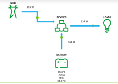
In AC support mode it looks like this (devices is the SW)

Capture+_2022-02-03-23-24-39~2.png
 
Manual says no N-G bonding in it, always relying on bond from grid connection. If that isn't present (off-grid), provide in another panel.
I don't know if it has split-phase output on one transformer core, or two 120V inverters synchronized each with its on transformer. your comment that it feeds less with imbalance suggests it may have one inverter driving split-phase transformer, which will act as auto-transformer.

Thx. I can power a 120v 1200w resistive load via the SW in ac support mode, and it will supply most of that 1200w from the grid due to the imbalance.

It was Schneider tech support that years ago encouraged me to try an external autotransformer to balance that 120v 1200w load, and when connected, it does indeed balance and begin to pull most of the load from the battery /inverter, supporting the grid.

But with all the discussion swirling around about N/G bonding, external autotransformers and safety it all has me wondering if Schneider steered me in the right direction for balancing the imbalanced loads to get their AC support mode to operate correctly. The way it was working out of the box did not square with their literature promises.
 
Depending on the load, if this is a permanent circuit such as a water heater rather than a plug-in item like a hair dryer, maybe you could use auto-transformer with neutral connected only to the load. That way, it presents a perfectly balanced 240V load to the inverter and grid.
 
Bottom-line, I’m trying to understand whether having an Autotransformer always connected or n parallel with the grid can cause a safety concern or not, and if that configuration can be used safely

2) If the autotransformer has breakers sized for its rating, and if the wire(s) connecting its neutral have ampacity 2x that breaker rating, it won't be a hazard. If it does draw more current than it can handle (trying to balance the grid) it will trip the breaker protecting itself. Just make sure your 120V loads fed by the autotransformer also get disconnected along with it.
there will be a idle/phantom random current with a permanently connected AT. It's random because it will try to balance whenever there's an imbalance, like somebody turns on a microwave/heater somewhere in the house. You can of course keep the AT Neutral separate from the main Neutral; but then will also need a separate ground rod .... not a safe configuration. It's too risky for my taste.
 
Back
Top