Goboatingnow
Solar Enthusiast
- Joined
- Jul 3, 2022
- Messages
- 1,325
Again gentlemen the general is independant grounds are not interconnected. One ground point per system.


DC shock Hazzards can also be deadly.But… aside from your inverter putting ac on your PV circuit (which couldnt even happen if your mppt and inverter weren’t the same box), why would the PV array need to be electrically grounded? Im still missing something.
and referring back to the OP question there is no "separate" grounding, run a ground wire back all the way.All the electronics inside the building was tied to it also. There was no separate "electrical" grounding.
So, i understand the normal DC hazards but I was not getting how tieing the PV frame to the house (aka AC electrical system) ground was making anything safer for the human because it didn't improve anything about you creating a 'path back to source' with your body.. On the DC side you'd have to have body parts touching something on both 'poles' of the DC circuit to get the juice flowing, in which case the ground conductor changes nothing because it's not tied to either one except in case of ground fault. So it wouldn't seem to reduce the DC hazard any in the absence of a ground fault.. But if one side HAS a ground fault, it increases the likelihood that you end up touching both sides of the circuit at once, because now the entire sea of panels you're standing in is one side of the circuit! The actual grounding rod at the house won't pull the DC voltage down because the dirt has no path back to the other side of the DC circuit, and if it did because BOTH sides of the DC circuit have a ground fault out to the panel framing, the panels would short locally through the racking and the ground conductor into the house would do nothing anyway.DC shock Hazzards can also be deadly.
Ground fault protection is also required for the PV DC circuits.

If you had a DC ground fault. The ground fault protection can't detect it and shut it down, if there is no ground.So, i understand the normal DC hazards but I was not getting how tieing the PV frame to the house (aka AC electrical system) ground was making anything safer for the human because it didn't improve anything about you creating a 'path back to source' with your body.. On the DC side you'd have to have body parts touching something on both 'poles' of the DC circuit to get the juice flowing, in which case the ground conductor changes nothing because it's not tied to either one except in case of ground fault. So it wouldn't seem to reduce the DC hazard any in the absence of a ground fault.. But if one side HAS a ground fault, it increases the likelihood that you end up touching both sides of the circuit at once, because now the entire sea of panels you're standing in is one side of the circuit! The actual grounding rod at the house won't pull the DC voltage down because the dirt has no path back to the other side of the DC circuit, and if it did because BOTH sides of the DC circuit have a ground fault out to the panel framing, the panels would short locally through the racking and the ground conductor into the house would do nothing anyway.
On the AC side you would only have AC out there if your house equipment was putting it there, and having a copper conductor back to house ground was just giving your pv panelling a BETTER path back to the AC source, than if you touched the live AC and a pv panel frame and that copper conductor wasn't there! X amount of AC voltage pushing against my body plus 150' of dirt resistance back to house ground rod back up into the panel to the NG bond, across the neutral back to source, is a lot less likely to give me the wiggles than my body plus 150' of beautiful perfect copper directly back to the source. So it would seem to me to be making the AC hazard worse.
I guess the way it could help is if it put the PV panel framing/racking at the SAME potential as the live wire you're touching. But that would require a 'ground fault', ie some low resistance path between the conductor carrying the AC, and the framing/racking. If there IS no ground fault, but you end up touching the AC anyway, and the PV panel frame, then the two things are at very different potential and you get the wiggles.
It just seems like ground faults are not the only type of fault, and this is making a bunch of other types of faults (including human error) more dangerous and only really helping in the event of lightning. I must have some major fundamental blind spot for all these downsides to somehow be wrong, or for there to be such a big upside somewhere else that it outweighs all these downsides. It's unnerving. I hope to get to the bottom of it soon.
I'm looking at my inverters diagram since it hasn't arrived yet (it's the EG4 6500EX) and I don't see any ground connection for the PV inputs. It's on page 19 of this manual. You can also see at this timestamp of Will's video that there is only the positive and negative PV connections, but no ground.And then the inverter is grounded to the service ground bar, hopefully.
Current imbalance detection does not need a ground to work.If you had a DC ground fault. The ground fault protection can't detect it and shut it down, if there is no ground.
Sorry, that's all that I have.
The only DC ground fault detection that I am aware of does not measure imbalance like AC detection. It looks for actual voltage on the ground.Current imbalance detection does not need a ground to work.
It's the same ground for everything. There's not a dedicated PV ground terminal. It just needs to be connected to the rest of the grounding system.I'm looking at my inverters diagram since it hasn't arrived yet (it's the EG4 6500EX) and I don't see any ground connection for the PV inputs. It's on page 19 of this manual. You can also see at this timestamp of Will's video that there is only the positive and negative PV connections, but no ground.
I have ran my ground through my attic with my positive and negative PV wires, going from my arrays to my inverters.

 www.fluke.com
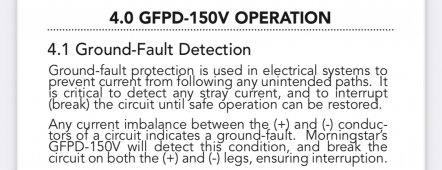
Nope , for example here’s Morningstar DC protection, it’s clearly stated it uses current imbalanceThe only DC ground fault detection that I am aware of does not measure imbalance like AC detection. It looks for actual voltage on the ground.
I see.Nope , for example here’s Morningstar DC protection, it’s clearly stated it uses current imbalance
I just spoke with Signature Solar who is the distributor of my inverter and they said under no circumstances should I connect a grounding wire from my solar arrays to my inverter. They said there isn't even a place to connect it because the only two ground lugs are for the AC input and output.It's the same ground for everything. There's not a dedicated PV ground terminal. It just needs to be connected to the rest of the grounding system.
That's what I said above.I just spoke with Signature Solar who is the distributor of my inverter and they said under no circumstances should I connect a grounding wire from my solar arrays to my inverter. They said there isn't even a place to connect it because the only two ground lugs are for the AC input and output.
It's the same ground for everything. There's not a dedicated PV ground terminal. It just needs to be connected to the rest of the grounding system.
Code requires minimum TWO ground rods at service connection point, and additional are approved. As long as all are connected together.Again gentlemen the general is independant grounds are not interconnected. One ground point per system.
Understood. So I can run this grounding wire from my panels and clamp it the the grounding wire coming off my service panel that goes into the earth ground rod?It's the same ground for everything. There's not a dedicated PV ground terminal. It just needs to be connected to the rest of the grounding system.
You can. A rod at the panels is recommended.Understood. So I can run this grounding wire from my panels and clamp it the the grounding wire coming off my service panel that goes into the earth ground rod?
If I were to do a rod at the panels, would I need to connect it to the main service panel grounding then?You can. A rod at the panels is recommended.
That depends on your SCC, and the panels. Some require a continuous ground conductor, some do not.If I were to do a rod at the panels, would I need to connect it to the main service panel grounding then?