diy solar

diy solar

Just blew both 200a Class T fuses after precharging with a 25w / 30ohm resistor…?

Hopefully they survived.. It does however has this in the manual:

CAUTION! Before connecting the DC circuit, ensure proper polarity of the system. Ensure the positive (+) terminal of the inverter is properly connected to the battery, and disconnect/fusing or breaker, as well as the polarity of the negative (-) connections.
 
? I think you guys are right about the reversed wires. I’m a bit in shock that this happened, having hired a solar veteran pro with good reviews. Everyone makes mistakes, I know.

Are these brand new units toast? Or is there a chance the fuses saved them? Or perhaps an internal fail safe?

I’m going back out tomorrow to check the terminal markings, but for now, I’m going to do some breathing exercises.

Thanks all, you’ve been so helpful!
The fact that you used fuses MAY have saved them. Most bms’s also have a pretty quick over current safety. But still, a total of 400+ amps! Check the markings for polarity and correct. Have an extinguisher ready, cross your fingers and try again with pre charge and engage. There may also be a fuse in the inverters by the way.
 
That 90W should be the beginning of a very short transient down to zero watts as the battery and capacitor voltages equalize. My precharge circuit takes about a second to get the inverter voltage to within 0.5V of the battery voltage. My resistor is way undersized compared to this one, and it doesn't even get warm to the touch, let alone hot.
For a 25W resistor to get too hot to hold in 5-8 seconds, as OP notes, it was probably at 90W that entire time. Which, as @sunshine_eggo says, should not happen.
There's got to be a short somewhere.
My 50 Ohm resistor gets pretty hot after about 15 seconds. I certainly cannot hold it any longer than that.
 
Before you touch it, call your installer and let him know about the mistake. You have a claim against him if the inverters are toast.
 
30 ohms may be too much resistance if inverter starts to conduct a large amount of current.

The pre-charging should not cause a pre-charge resistor to get hot. It takes continuous current from inverter circuitry drawing moderate amount of current.

Inverter should not be setup to start in active mode with inverter putting AC output. This will draw too much initial idle current. It should require user intervention to activate AC output on inverter after control screen comes up. Jumping right into active inverter mode is a safety issue if there is external AC overloads when unattended.

With too large of pre-charge resistor value, the inverter may get into a zone where high power MOSFET's gate drivers are not getting enough supply voltage to hold the MOSFET's fully off, resulting in them dribbling a significant amount of current holding the DC voltage low with voltage drop across the pre-charge resistor. This also causes the pre-charge resistor to get hot.

I would recommend a 2 ohm pre-charge resistor. That limits current to initially about 25 amps and should cover any initial idle power of inverter. With just the controller, display, and possibly the pass-through relay powered, the DC current should not be greater than an amp. You will only need about a couple tenth's of a second to pre-charge inverter input capacitors, with 2 ohm pre-charge resistor, before you flip on DC breaker.

The main purpose of a pre-charge resistor is the avoid degrading circuit breaker contacts or tripping BMS overcurrent limit due to the approximately 3000 amps of initial, very short time period, input capacitors initial charging current.
 
Last edited:
30 ohms may be too much resistance if inverter starts to conduct a large amount of current.

The pre-charging should not cause a pre-charge resistor to get hot. It takes continuous current from inverter circuitry drawing moderate amount of current.

Inverter should not be setup to start in active mode with inverter putting AC output. This will draw too much initial idle current. It should require user intervention to activate AC output on inverter after control screen comes up. Jumping right into active inverter mode is a safety issue if there is external AC overloads when unattended.

With too large of pre-charge resistor value, the inverter may get into a zone where high power MOSFET's gate drivers are not getting enough supply voltage to hold the MOSFET's fully off, resulting in them dribbling a significant amount of current holding the DC voltage low with voltage drop across the pre-charge resistor. This also causes the pre-charge resistor to get hot.

I would recommend a 2 ohm pre-charge resistor. That limits current to initially about 25 amps and should cover any initial idle power of inverter.
They determined the problem.
 
Hi all,

After watching Will’s many videos and searching on the forum, I’m still perplexed by what’s happened with this system today. I had two brand new EG4 6000ex’s installed this morning, with 8x Rich Solar 12v/200ah batteries wired in two parallel 48v banks (batteries were already here from previous build, otherwise I would have opted for 48v units instead).

After spending all day wiring it all up, it was finally time to power it on. The electrician jumpered the battery switch posts with the resistor (25w/30ohm) for 5-8 seconds, at which point he stopped due to the resistor getting too hot to hold.

When he activated the battery switch, we were greeted by sparks within the switch and found that neither inverter would light up. Further inspection would show each of the 200a Class T fuses blown.

Our guess is that we didn’t precharge long enough? In all the YouTube viewing I’ve done on the subject, 5-8 seconds seemed like enough time. Perhaps we were wrong?

A couple questions for you guys:

1. Is it because we have two inverters, both with caps that are making the precharge take longer?

2. Are the fuses large enough at 200a?

3. I’m still confused as to how with the amount of precharging we did, there was still enough current to pop two 200a fuses?

4. If 5-8 seconds wasn’t enough, how much is? Should I measure amps with a DC clamp meter and precharge til the current reads 0?

5. Should I be worried about any potential damage to these virgin inverters?

Thanks in advance. I’m guessing this is a super elementary question for all the more experienced folks here.
What kind of resistor? What size? What wattage?

12000W capability, a pair of 200’s seems right.
Something else is wrong.
Post detailed pics of the wiring, and the setup. I can’t tell much from the one pic.
 
I would recommend a 2 ohm pre-charge resistor. That limits current to initially about 25 amps and should cover any initial idle power of inverter. With just the controller, display, and possibly the pass-through relay powered, the DC current should not be greater than an amp. You will only need about a couple tenth's of a second to pre-charge inverter input capacitors, with 2 ohm pre-charge resistor, before you flip on DC breaker.
A 60 to 100 Watt, 120v light bulb works great. You should see it barely glow for a fraction of a second. If you see it continue to dimly glow after a few seconds, you should stop and check your wiring. I use a porcelain base so I can just set it on the floor.
 
? I think you guys are right about the reversed wires. I’m a bit in shock that this happened, having hired a solar veteran pro with good reviews. Everyone makes mistakes, I know.

Are these brand new units toast? Or is there a chance the fuses saved them? Or perhaps an internal fail safe?

I’m going back out tomorrow to check the terminal markings, but for now, I’m going to do some breathing exercises.

Thanks all, you’ve been so helpful!

We've all done something like this. When I have, and ckt. protection blew, I start carefully and methodically checking each and every component one at a time. Batteries individually, then in whatever XSYP config you are using. You might wanna replace the battery switch since you said "we were greeted by sparks within the switch". That means there's carbon tracking inside now.

Fire the inverters individually with no load, when I first do this after an "event", I use a 20A fuse so it'll blow quickly if something's FUBAR. You'll still need to do the pre-charge or that small fuse will blow. If you eventually get displays on the inverters and can run through some config, you can then "upgrade" to the 200's and throw a NON-CRITICAL load (in case you get non-compliant AC output) on. My go tos for "non-critical" are blow dryers and hot pots. Something resistive - no complex reactive loads until the simple ones work.

Of course you are measuring the crap outta everything (current and voltage) at each and every step with a clamp DVM. And what I present here is the bare minimum - you can certainly take things to an even higher level of testing and checking. It might be that the application of reverse polarity has nulled out any warranty and/or UL/whatever certifications there may have been.

When your system is back working, put it to work running non-critical loads (no CPAP machines, for instance) for a few weeks. Keep checking with the DVM.

If things go OK, it is up to you at this point if you want to trust everything.

Of course, it your sparky "mans up" and accepts responsibility for the whole shebang, hand it off to him. Again, it's up to you whether you twist arms for a total replacement of anything that might have been affected. It's all about having a safe system going forward.
 
A 60 to 100 Watt, 120v light bulb works great. You should see it barely glow for a fraction of a second. If you see it continue to dimly glow after a few seconds, you should stop and check your wiring. I use a porcelain base so I can just set it on the floor.
On my 48V UPSverter I also precharge with a 60W incandescent light bulb. It will light for a good 2-3 seconds as the 3kva UPS caps are pretty big.

In my opinion an incandescent bulb is the perfect variable-resistance load, plus includes visual indication. The typical resistance when off is 24 ohms, and when lit is 240 ohms.
 
Last edited:
It’s surprising how little it takes to pre charge some inverters(LV6548’s) I have a two pole 200 amp breaker and I thought I’d be smart guy and use an LED to tell me(remind me) the there’s a voltage differential between the open breaker and the inverters. Used a diode from each output of the breaker, voltage dropping resistor and the LED. Connect it and all looked good. Hey why is that LED dimming? Oh smack! R U kidding me? That little LED was partially charging the inverters! Rummaged through my junk and found a LED that I couldn’t measure any current in use and that worked and let the inverters discharge when not in use, yet would light.
 
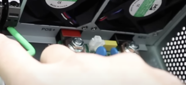
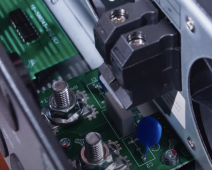
I would be interested in a macro shot of the battery connection posts for this inverter. Wondering why this happened.
 
I did find a 6500EX pic (not the 6000ex that this thread is about):
View attachment 154092

Okay, that's pretty clear, if it's also indicative of the 6000 we're talking about. Color coding on the studs and polarity labeling on that bracket. Was there any further info under the "hand" (if it's yours)?
 
Those pics were both from screen grabs on YouTube. Last one is video from SignatureSolar itself:
 
Back
Top