MrM1
I'm Here, But I'm Not All There
I get 0.000 OHMs across +/- inverter terminals


Yes.... my lack of electrical knowledge too. But when I have just the charge controller external connected there is no continuity between positive and negativeMaybe it's just my lack of electronic knowledge, but of course there's continuity there. The pos/neg come together within the components of the inverter. If you had no continuity I would be worried.
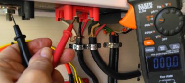
Actually, when I put the meter across the inverter positive and negative it starts at 0.2 then drops to 0.1 and then to 000 across inverter +/-
Across the busbar with inverter DISCONNECTED and scc connected I get no reading ... Just DL on the meter
View attachment 136683

I’m not sure about the DVM EP.Interesting. Especially the current idea.
My question still is, should the DVM beEp when touched across +/- at the inverter with inverter disconnected?
Everything else is powering up and working correctly , ( my powering up I mean the solar charge controller is coming on when battery voltage is applied) voltage is as expected all the way to the bus bar before the inverter. I have the solar charge controller connected to that bus bar, I just have the inverter disconnected and am afraid to connect it.I’m not sure about the DVM EP.
If you’re at a dead end and everything else checks out, that’s when I’d start looking for loose/frayed/corroded cables. I don’t think powering it up and blowing two $25+ fuse until something is found is a good idea.
I have a 9 panel portable panel array and I constantly deal with loose connections. Sometimes an Anderson Plug connector has worked itself out, other times wires have worked themselves out of circuit breakers, other times a wire has come loose from a combiner. Once had a poor connection at a plug and it melted.
A 12 volt load, like a 12 volt light or something? I really do not understand this. What would cause it to operate and have voltage? The capacitors of the inverter?Save your fuse. Put a 12V load in series with your inverter connection (basically in place of the fuse). If the inverter is shorted the 12V load will have full power and operate just like it was tied to the battery. While this is pulling some current you can measure the voltage drop across the inverter and across your 12V load. If the inverter is shorted it's voltage drop will be near zero.
Think of the inverter as a short. It will complete the path to one side of your power, the other side will run to the load. If the inverter was open, your 12V load wouldn't work. Good news here is that you can't blow anything up. An old car lamp will work (just not LED).
LET ME TAKE THAT BACK, I SEE THAT YOU ARE A 48V SYSTEM, YOU NEED A 48V LOAD.
This load is placed in series with the battery leads, for testing only. It will allow you to energize your inverter without risking your expensive fuses yet still limit current to a low value. Your battery powers the inverter once its caps are charged, but you won't be able to apply much of a real load.But does there need to be a battery in that? What powers the light or load?
Got it.Yes, you need a battery. Think of it this way. It's like a pre-charge resistor. In this case if your inverter is shorted, it won't charge up but at the same time instead of blowing a fuse the pre-charge just gets warm.