diy solar

diy solar

Crap ~ Both my 225 amp Class T Fuses Blew

Did the Victron shunt record anything interesting?
Can't tell right now because it has no power. It lost power when the fuses blew.

But I did notice the little in line fuse in the shunt power wire was still good.
 
Can't tell right now because it has no power. It lost power when the fuses blew.

But I did notice the little in line fuse in the shunt power wire was still good.

Once you get some power to it, the logs might tell you how long it was "running" before it blew. Would also show reduced voltage, maybe the peak amps.. who knows. That thing might be a goldmine.
 
Once you get some power to it, the logs might tell you how long it was "running" before it blew. Would also show reduced voltage, maybe the peak amps.. who knows. That thing might be a goldmine.
I certainly will check that
 
Pleasantly surprised ... The fuses that were supposed to be here Tuesday came yesterday. So I'm headed to the farm this morning to see if I can figure out what happened.

Any suggestions on what tests I should make and things to look for?
-I'm still thinking something with pre charge
-or capacitors
-but where would I be looking for shorts?
-how can I test the inverter for shorts internally?

The blown fuses needed are two 225s, one for each battery. I now have 4 new ones, but I don't just want to throw 2 in and have them blow right away
 
Another scenario that could have happened.
When they powered everything back up. The capacitor surge was enough to shut down the BMS's. But, one of them wasn't fast enough to save the fuse. Then after 10 minutes of running. The loads were enough to take out the second fuse. Although, the BMS should have saved the second fuse. Assuming that the BMS limit is lower than the fuse rating.
Yup agreed. And thx, lots of options.

In theory, the bms should shut down b 4 the fuse at 200 Amps, but if it was quick it got the fuse first.

Shame you're not in central FL, I'd call in a favor ?
 
I'll be in the area in June. But, I don't think that you want to wait until then. lol
 
Going from memory here, but this would be my initial test procedure:
  1. Visual inspection to look for damage, test fuses, document as-found voltages at various parts in the system.
  2. Check continuity across pre-charge switch and make sure it matches its expected mode.
  3. Shut down all equipment to the extent possible.
  4. Check 400A fuse; remove to test upstream.
  5. Jumper over fuses with small test leads and check pre-charge sequence and voltages throughout system; keep inverter and mppt shut off.
  6. Assuming all is normal, re-install fuses and repeat previous test.
  7. Perform visual inspection on PV connections to trailer, check voltages.
  8. Perform startup.
What test equipment do you have? Generally the more information you can record the better.
Thx

All I have with me is a Klein c390 dvm
 
I have continuity across the positive and negative of the inverter!

I don't think that's supposed to happen
 
I've got continuity between the inverter input positive and negative, and the PV input positive and negative. also have continuity between pv input positive and negative while connected to the inverter aio
 
I remove all pv inputs +/- and there is no continuity between pv.

Still have inverter in +/- continuity
 
Maybe it's just my lack of electronic knowledge, but of course there's continuity there. The pos/neg come together within the components of the inverter. If you had no continuity I would be worried.
 
Actually, when I put the meter across the inverter positive and negative it starts at 0.2 then drops to 0.1 and then to 000 across inverter +/-

Across the busbar with inverter DISCONNECTED and scc connected I get no reading.2.Just DL on the meter

IMG_20230225_102133.jpg
 
Maybe it's just my lack of electronic knowledge, but of course there's continuity there. The pos/neg come together within the components of the inverter. If you had no continuity I would be worried.
Yes.... my lack of electrical knowledge too. But when I have just the charge controller external connected there is no continuity between positive and negative

This is like the battery positive and negative we're touching each other which I'm guessing is why the fuse blew. But I have no idea on that unless I go home and check my own inverter
 
Looks like your portable build is in your signature block. Very nice.

I’m sure you’ve tested for something as simple as cables loosening during the trip?

In my limited experience, the parallel batteries will not provide a perfectly equal load no matter how much care you give in making the wires. A few percentage points away as measured from each BMS is reasonable and highly unlikely 1% will be reached. Any loose cable under load would give a bit of resistance, more under load, and drop the voltage at the inverter and increase the amperage needed to run the load at the same wattage.

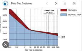
That could cause a thing where the total draw is 400 amps but 250 amps is pulled from one side and 150 amps from the other, although a BMS should trip if the fuse doesn’t. A class T fuse can take a bit of time to trip if just barely over the limits.

DEA9AFD6-7090-44AB-BE6F-7634106FEDC1.jpeg

A loose cable would not show on a continuity test; its close enough to 0 ohms that minute current won’t change enough to make the beep go off or to show on any ohmmeter I’ve ever tried.
The other thing I’ve seen cause problems like this is a cable fraying internally and corroding in a place not visible until parts are pulled away so the whole run can be seen.
 
Interesting. Especially the current idea.

My question still is, should the DVM beEp when touched across +/- at the inverter with inverter disconnected?
 
I just don't want to hook it back up and blow another fuse for no reason

But I'm also not excited about reaching out the signature solar for warranty or tech support. The wait times are horrible
 

diy solar

diy solar
Back
Top