Zwy
Emperor Of Solar
Nice diagram, did you draw it up?
Nice diagram, did you draw it up?
There isn't even a panel. Solar array -> DC Disconnect -> Inverter (which also has a DC Disconnect) -> AC disconnect -> to a back fed breaker in the main service panel on the pole. The garage still has no grid service and is basically just a ground mount structure in this application.Ok, a structure is slightly different. The panel in the garage should have a ground rod but should not have a N-G bond. The ground rod should be located at the garage panel, not at a ground mount array. There needs to be a ground wire, 6AWG minimum between the garage and main service panel.
I have no artistic skills, so I used the stock example from my provider and photoshopped the heck out of it.Nice diagram, did you draw it up?
There isn't even a panel. Solar array -> DC Disconnect -> Inverter (which also has a DC Disconnect) -> AC disconnect -> to a back fed breaker in the main service panel on the pole. The garage still has no grid service and is basically just a ground mount structure in this application.
It was a nice diagram, I really liked it as far as having 2 structures.I have no artistic skills, so I used the stock example from my provider and photoshopped the heck out of it.I am trying to offset my 13ish kWh daily grid usage. This system was inexpensive and a lot fun to put together.
I have 48v 100 Ah Lithium Iron Phosphate batteries with the sungold 10kw inverter. I have my battery type set to “user” because there in no preset for lithium. Would these values be good for me also? I’m not connected to the grid. Thanks.My current settings.
01 - SBU
02 - 60.0
03 - UPS
04 - 49.2
05 - 50.8
06 - SNU (grid breaker is off so OSO)
07 - 180
08 - USER
09 - 55.6
10 - 90
11 - 54.8
12 - 45.2
13 - 15
14 - 49.6
15 - 42.4
16 - dIS
17 - 21 irrelevant, 16 disabled.
22 - dIS
23 - 27 - ENA
28 - 5
30 - Id: 4 (changed this when SA was having connection issues)
32 - SLA
33 - WOW
34 - dIS
35 - 50.4
37 - 54
38 - 120
40 - 45 - not used 00:00:00
46 - dIS
47 - 52 - not used 00:00:00
53 - dIS
54 - 55 time and date
57 - 4
63 - dIS
68 - 180
Will hit 3.5mWh today or tomorrow pending sun...
View attachment 203963
Welcome to the forum Brian.I have 48v 100 Ah Lithium Iron Phosphate batteries with the sungold 10kw inverter. I have my battery type set to “user” because there in no preset for lithium. Would these values be good for me also? I’m not connected to the grid. Thanks.
Just disconnect the BMS communication cable
As long as the BMS charging profiles aren't aggressive I'd have no issue using communications. It seems most of them try and charge to 3.6xV / cell, which is completely unnecessary based on what I've read and understand.So there are 2 philosophies here.
Some use the BMS communication to have the BMS in control of charging etc.
And others don't. They may make operating decisions based on voltage (instead of SOC).
I personally am in group 1, which may be the minority based on number of postings.
Not using BMS communications allows you to mix batteries from different manufacturers and some have advanced setups with Solar Assistant.
. It seems most of them try and charge to 3.6xV / cell
Nice. Good for SGP.Mine shows 100% at 56.4V that's 3.525V per cell.
All equipment is from SGP, November-December 2023.
Nice. Good for SGP.
You don't have any cells are running that would trigger 100%?
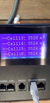
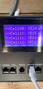
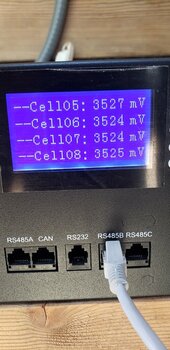
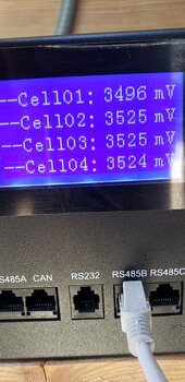
Very nice.I haven't seen an OVP status in months, since this forum told me how to put the comm cables properly in.
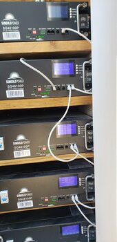
Here's the photo showing all 5 "full"
View attachment 228087
Cell voltages of the top most battery. The lowest I saw on other batteries was 3512mV, nothing over 3527mV.
View attachment 228088View attachment 228089View attachment 228090View attachment 228091
Disconnect the cable before I change the parameters? Or leave it unplugged?Welcome to the forum Brian.
I was just getting to reply to your other posts with my settings you already found, nice work searching.
I'm nearly 100% confident these settings would work fine for you. Just disconnect the BMS communication cable.
I would disconnect before making the changes. You will probably get an error/fault on the display, I can't confirm because I've never used comms, don't panic if you do.Disconnect the cable before I change the parameters? Or leave it unplugged?
I made all of these changes, and as I had an error before I even started, it is still there. I did put the communications cable into the “RS485 A”port, and all subsequent connections between batteries into the B and C, as was suggested, but that did not change anything, the error is still thereI would disconnect before making the changes. You will probably get an error/fault on the display, I can't confirm because I've never used comms, don't panic if you do.
I made all of these changes, and as I had an error before I even started, it is still there. I did put the communications cable into the “RS485 A”port, and all subsequent connections between batteries into the B and C, as was suggested, but that did not change anything, the error is still there
You've tried a reboot?I made all of these changes, and as I had an error before I even started, it is still there. I did put the communications cable into the “RS485 A”port, and all subsequent connections between batteries into the B and C, as was suggested, but that did not change anything, the error is still there
Is the BMS to Inverter cable connected to the battery with address 1?You've tried a reboot?
For me it’s just a goal and something to mess with along with my DIY packs. Have it mostly working. However one reason was when a large load caused enough voltage sag to make my inverter think I had nothing left in batteries and shutdown. That was my pack issue I needed to resolve.Can anyone honestly come up with a REAL reason to run comms aka bms connected to the inverter vs non comms?
My batteries cannot do comms and I haven't ever stood in front of my inverter saying "Damn I wish I could connect my batteries bms to my inverter"
The victron shunt has a dead accurate SOC that is what my system uses to know the SOC. BMS's are not accurate at ALL on SOC. So again is there a REAL reason? Any reason?
But if you had a shunt like the victron one it wouldn't have been effected. It doesn't go by voltage.For me it’s just a goal and something to mess with along with my DIY packs. Have it mostly working. However one reason was when a large load caused enough voltage sag to make my inverter think I had nothing left in batteries and shutdown. That was my pack issue I needed to resolve.
I have a Victron shunt now. One of the ESP32 projects I’m using translates that into CANBUS over pylontech. I’m not at this location all the time so it’s easy to use one tool to view overall system status.But if you had a shunt like the victron one it wouldn't have been effected. It doesn't go by voltage.
Doesn't your inverter have a low voltage delay timer?For me it’s just a goal and something to mess with along with my DIY packs. Have it mostly working. However one reason was when a large load caused enough voltage sag to make my inverter think I had nothing left in batteries and shutdown. That was my pack issue I needed to resolve.
Not that I’ve seen on the EG4 6000xp by Lux. No issues now with custom CAN for DIY pack.Doesn't your inverter have a low voltage delay timer?
Maybe this winter when I get bored I'll work on comms with my JBDs.Not that I’ve seen on the EG4 6000xp by Lux. No issues now with custom CAN for DIY pack.


