diy solar

diy solar

SunGold Power SP6548 Flickering lights after new install

What about a small dedicated pure sine wave inverter just for lights? I suspect every light in your house adds up to less than 300 watts
I don't think that is an option in most USA homes as the lighting circuits are connected to the room outlets in most cases. However, in a new build that is definitely the way to go and I will be doing that.
 
Like my house! All the downstairs lights are on a circuit together with the office outlets, because that makes sense.

And my bathroom outlets are all on one circuit, but the master bathroom lights are separate. Because that makes sense.

I'd like to know who decided to lay out the circuits in this house :rolleyes:
 
I was under the impression that Voltronic made Growatt, MPP, the EG4 units and SunGold Power. https://voltronicpower.com/ Would also make sense since they offered to swap the unit for something from one of the other names above.
I am not sure about Growatt, I feel they are a separate copy cat company, but yes the EG4, LV6548, SP6548, Sophos 6548 etc are all the Axpert-MAX-7.2K Interesting to note the 240v version comes with the 500v PV inputs so EG4 must have persuaded them to add that MPPT into their EG4.
 
That is exactly my issue. The majority of the first floor lighting is tied into the family room outlets. Kitchen cans are tied into the dining room lights and receptacles. It makes 0 sense but that's how the do it in the US. I really don't have that option unless I rewire the house and that isn't happening.
 
I would be OK with an inline isolation transformer but I can't find anything meant to be hardwired under 1k. Just doesn't make sense to put a 1k bandaid on a 1.3k inverter.
 
JWalters comments about changing the fans removing the flickering for him are interesting. Since the fans are dc driven and pwm controlled I am wondering if the conducted EMI is making it's way back to ground or power which is then amplified by the inverter and showing up on the output. Using lower RPM fans like he did will change the frequency and perhaps put it outside of the range of the inverter. Or, since the fans are higher quality Noctua units they likely have proper shielding and limit UMF radiation.
Since I have been told it's going to take weeks for answers I am going to pull the original fans and run some tests. I have also noticed in review images that MPP and EG4 are using the same fan manufacturer in all the reviews. But, JWalters MPP unit and these Sungold units are all using the YCCfan model. Coincidence? If this was an issue with all LV6548's I'm sure there would be many more complaints. Deeper down the rabbit hole we shall go.
 
I have done some testing and a video will be up shortly, teaser WTF waveform is this ???
 

Attachments

  • IMG_20220803_113453880_HDR.jpg
    IMG_20220803_113453880_HDR.jpg
    120.1 KB · Views: 17
In case anyone cares about how a dimmed LED waveform looks plugged into a regular mains power outlet.
 
Something is up.. nothing would run off that waveform. Also the first waves looked like modified sinewave.. weird. Is the power supply isolated? I used an isolated power supply and connected my scope to hot and neutral not just 1 leg.
 
Last edited:
Looks like a standard trailing edge dimmer to me. Originally (incandescent) dimmers were leading edge, the triacs or scr was turned on at some time in the cycle. As low voltage (MR16, etc BWOE) and florescent became more prevalent dimmers were redesigned as trailing edge to be compatible with the LV and electronic transformers. Most dimmers now are trailing edge and it is the driver circuit in the led that interprets the "on" time of the incoming power cycle and converts it to an intensity level for the led chips.
 
Don't show that inverter output to the inverter company or they will never listen to another thing you have to say. You have a floating neutral. That is totaly the way I would expect it to look given the way you measured it. That should be measured thru a transformer.
 
It is wired as per the manual except totally off grid, panels and battery only. The Sol-ark you see me scoping in this video and the Growatt I have previously tested are wired the same way, 100% off grid solar and battery only. They produce lovely sine waves.
 
What is the power source for the scope? Needs to be a separate pure sine clean source. So grid with an isolation transformer or it can be the solark if its not sharing any connections. Probe the hot and neutral and try again. Something is not right there. As much as I would love more information for them to fix the issue I feel something is amiss in this methodology.
 
Might have solved the issue! Right now I am only taking in 70W from the panels. Reevaluate tomorrow then I will post what I did. If this fix holds with more PV input it's incredibly simple and cheap to implement.
 
What is the power source for the scope? Needs to be a separate pure sine clean source.
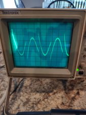
At the start when showing calibration of the probe, at first I was connected to the inverter and it was putting spikes on the square wave, so I connected the scope to the house supply. If all 3 of my inverters are wired the same way off grid, why do 2 give lovely sine waves and the 6548 a horrid mess ?
 
Unsure how those are wired. Just saying how I tested it to compare apples to apples. 99% certain the problem has been resolved. Tested everything that has been giving me problems and so far no issues. Need to bring a scope home from work.
 
I had exactly the same thing happen with my LV6048 inverter. All of my LED shop lights flickered periodically, and for no apparent reason. Then I installed 2 LV6548s and the problem went away. I isolated and captured the problem on an oscilloscope trace - it's periodic noise on the output of the inverter sine wave that is the culprit.

normal trace of 120v inverter output, no flicker:
88A5E157-5956-4C7E-81D3-C22ED2C8A820.jpeg

Periodic noise (no cause that I could find) induced by the inverter at periodic intervals:

B9085552-2A2D-43C9-8907-8913BC193007.jpeg

THIS is what causes the flicker. Get rid of the noise on the 120v line and the flicker will go away as well.

As a kid I was the renowned Bay Area expert in eliminating engine noise in massive car stereo systems in the 1980's. Looking at the traces on my scope, this is literally no different. It's line noise. Before getting the LV6548s I ordered a 20amp line filter that should eliminate this problem. They make a 50amp version as well but I was going to try it first on the light circuit just to be sure it solved the problem, then filter the entire 50a output. Note this would require 2 50a filters, one for each 120v leg. Or just use the 20a filter on the light circuits.

this is what I ordered:
line filter

D6F64B5C-B223-40CF-8BF7-4132C820CCF9.jpeg
Now, I have it, but never tested it bc I ended up installing the LV6548s for my shop and house and they don't suffer from this issue, but based on the scope traces it should fix the flickering problem. For $16, it certainly might be worth a try?

anyone else tried this???

Jeff


.
 
Last edited:
It is certainly worth a shot. Getting 4ga wire on that would be interesting lol. The issue is this is not periodic noise or induced by other items on the circuit, it is constant. We should not have to noise filter 6.5kw of output to use an inverter with lights or a UPS.
I have used those filters in the past, they work well just be sure to ground them. Other big issue is they are not code compliant in my area.
Should have a decent idea today if my "fix" actually works. Fingers crossed.

Something like this would be easier to implement if you were filtering just a lighting circuit but deff not going to pass an inspection with it installed. inline filter 6A
 
Last edited:
You need a digital scope that will display at least 5 seconds of waveform. Then at the location of an anomaly it can be expanded to see what is happening. Flickering will be caused the AC waveform being modulated (varying amplitude). A little waveform distortion will not cause the flickering on a non dimmed LED.
 
General waveform distortion no, but those spikes could cause a power supply transistor to conduct more and cause a spike in the regulated output.
I'm thinking supply chain and labour issues are causing corners to be cut in order to deliver goods.
 
General waveform distortion no, but those spikes could cause a power supply transistor to conduct more and cause a spike in the regulated output.
I'm thinking supply chain and labour issues are causing corners to be cut in order to deliver goods.
I tried using an Xstar V4 18650 charger off the inverter a few days back but the transformer was letting out a whine and the display was flickering. Switched it back to bypass, no issue. Just going to leave it there until we get an answer from Sunpower. Most other ac/dc chargers I tried worked just fine though. Charged a few Ego batteries off it no problem. Feels like a waste having the 48v pack charged and pv available but not using it. At least the lawnmower and trimmer will be running off sun juice.
 

diy solar

diy solar
Back
Top