diy solar

diy solar

240V V2L from North American Ioniq 5

Some hard facts in no particular order (some of which repeat zanydroid already said, sorry). I own an EV6, and have personally tested/measured/opened and observed all of these things except where indiciated. I have a USA car, so keep that in mind also:

  • The EV6/Ioniq 5 use a bidirectional ICCU (integraded charge controller unit) to drive their V2L capabilities, i.e. can't be used while charging.
  • The interior and exterior outlets are wired together. Not QUITE directly - I think the interior has a relay that can disable it independently based on whether a plug is physically present, probably for child finger reasons. I'm not actually certain the outlets share the same power path/phase, but I AM certain they share the same overcurrent limit (tested). It's 15A total, not 15x2. 1.8kW max USA, 3.6kW elsewhere where the standard mains is 230 or 240.
  • The V2L output depends on the region of the car, not the connected (passive) adapter. Korea and USA share J1772 as a charge standard, so the 230V korean adapter plugs into USA cars. But you get 120V 60Hz out, not 230.
  • I say (passive) adapter because (future? WIP? not sure) V2L standards will include (I believe) powerline communication for connection management. I have to assume a proper bidirectional EVSE that actively communicates by such a mechanism could get 240V out of the north american configuration.
  • The V2L adapter is very simple and you can cheaply build your own. Multiple people have, though I'm struggling to resurface the threads. It's basically a J1772 (or type 2) plug and a couple resistors, VERY close to an actual J1772 cable but with the PP and CP pins shorted together to indicate "output please"
  • CHAdeMO has always "supported" V2L, but I believe only DC-out V2L. I.e. there's standardized communication for the function, but you still need an EVSE with a fat stack of (expensive) inverters in it, a-la bidirectional CCS as well.
It's pretty unclear to me how Hyundai intends to support V2H or V2G on the current crop of cars. I'm certain it is/was intended, but absent robust standards maybe the intend to roll out a software update to support it, maybe not? The biggest issue in the USA is that the plug only has hot/neutral/ground, so it's impossible to support a backup V2H situation without an (auto-or-traditional)transformer external to the car. This is not necessarily an issue in Type 2 regions, but I don't know whether the ICCU supports 2 or 3 phase output either. I'd assume so but not yet publicly known.

As for solar harvesting, looked into that pretty extensively too. Some more relevant facts:
  • The car uses negligible power in sleep mode, on the order of a percent every few weeks
  • When charging, on, etc, the electronics draw minimum 300W.
  • A tesla, by comparison, consumes about the same 300W, which is why Sentry mode is such a power sink.
  • This is a huge killer for low-power charging efficiency. The minimum to even play ball is 300W burned right off the top doing no charging at all, so if you had a 600W array, you'd be talking 50% charging efficiency before even considering any other losses.
  • The J1772 standard doesn't support indicated capacity lower than 6A (at least with basic PWM communication), so you can't even START charging with less than 720W, 300 of which as mentioned is wasted. Not sure how the Type 2 standard compares.
  • This all implies that "DC slow charging" would be great, but absent a very specific power mode being supported by the car (like whatever the European solar roof Ioniq 5 variant does), you'd still be stuck with the 300W loss off the top.
 
Sorry to resurrect an old thread here. I've been wondering about the V2H bi-directional EVSEs. Could this be done in a car model independent way? From my understanding there is some hand shaking communication between the EVSE and car to prepare for DC charging. If the car's happy it closes the relays to connect the DC port of the charge connector directly to the battery. Could an EVSE tell the car it wants to L3 charge, cause it to connect the battery, and then draw from the battery to power the 800VDC -> 240VAC inverter? The car firmware would see that the current was flowing out -- wonder if it'd open the relays?

Oops missed this question, took a few months off from this forum.

CCS2 is supposed to have a profile that will connect the battery (with potentially DC-DC conversion to an agreed on voltage, probably best to output a 600V or lower voltage to be more compatible with standard inverters and 600V wiring methods. Not sure what the line diagram looks like, and I don't know where to get the standards for free).

As for trying to do this with CCS, when I checked on DIY EV forum, very few people (zero in fact) in the business were willing to help people figure out how to do this. Some folks I talked to on other forums thought the BMS or other safety mechanisms on the car might get cross. Maybe a few cars would work in this hacked mode without complaining.
 
CCS2 is supposed to have a profile that will connect the battery (with potentially DC-DC conversion to an agreed on voltage, probably best to output a 600V or lower voltage to be more compatible with standard inverters and 600V wiring methods. Not sure what the line diagram looks like, and I don't know where to get the standards for free).
Given how cost effectively high voltages can be transmitted wouldn't it be amazing if a standard were to come into existence for 300 to 500v DC? Think about it, we could run a 10 AWG THHN wire pair right next to your AC panel and jack it into your next generation inverter (like a sol ark) that would be smart enough to charge your EV and use it as a disaster avoidant generator.

If we could just keep voltage levels to lower than THHN I think this could be come standard. Given that there are many more cheap cars made that could use these lower voltages than expensive ev's that may need higher voltages, this seams like a possible future reality. Could even move us in the direction of getting rid of AC charging of EV's.

Another option would be to have those really high voltages come into special car chargers that have DC BUCK and boost from the 500Volt max DC transition lines to the required voltage for the vehicle? The less stuff in the vehicle itself the lighter, faster, cheaper, etc it becomes.
 
Last edited:
Given how cost effectively high voltages can be transmitted wouldn't it be amazing if a standard were to come into existence for 300 to 500v DC? Think about it, we could run a 10 AWG THHN wire pair right next to your AC panel and jack it into your next generation inverter (like a sol ark) that would be smart enough to charge your EV and use it as a disaster avoidant generator.

If we could just keep voltage levels to lower than THHN I think this could be come standard. Given that there are many more cheap cars made that could use these lower voltages than expensive ev's that may need higher voltages, this seams like a possible future reality. Could even move us in the direction of getting rid of AC charging of EV's.

Another option would be to have those really high voltages come into special car chargers that have DC BUCK and boost from the 500Volt max DC transition lines to the required voltage for the vehicle? The less stuff in the vehicle itself the lighter, faster, cheaper, etc it becomes.

Incidentally I ran into some new-to-me info about the Ford Charger Pro, and started this thread on Reddit.

That charger appears to be little more than a L2 EVSE + CCS2 trigger interface. It connects to a hybrid inverter via RS485 and 600V DC wiring. #8 THHN for about 100A worth of backup power.

There is a pointer in there too to dcbel's single line diagram.


Personally I doubt there will be a DC coupled standard any time soon. Based on my limited knowledge, barely anything can interop over serial these days. Also UL likes to qualify an integrated system (battery + inverter).

AC coupled system probably supports more interop due to UL1741SA, albeit janky because there's only so much that can be signaled that way.
On the electrical side, technically this is great news. A simple voltage monitor that senses a low voltage on a 48v DC battery could flip a relay connecting the x00v power source to a DC buck device with constant current. Once it detects your programmed top voltage it disconnects the relay.


For a 20 amp DC device I could see those electronics coming in at under $100 if mass produced.
40 amps 150
60 amps 200
Etc.

We just need standards for home power storage and we are promptly heading that way ?
 
DC-DC Buck Converter Step Down Module, 30A 800W High Power Constant Voltage Module 12V24V36V48V Adjustable Buck Converter Step Down Voltage Regulator Module https://a.co/d/7ABQPd1

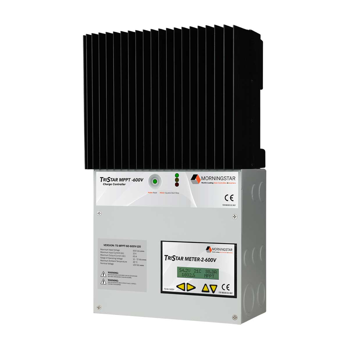
This input is too low. Perhaps a device like a solar charge controller could handle this given its high voltage input.

Anyone with experience?


I found this one.
 
DC-DC Buck Converter Step Down Module, 30A 800W High Power Constant Voltage Module 12V24V36V48V Adjustable Buck Converter Step Down Voltage Regulator Module https://a.co/d/7ABQPd1

This input is too low. Perhaps a device like a solar charge controller could handle this given its high voltage input.

Anyone with experience?
There are various posts out there about testing MPPT inputs on a lab bench with a DC power supply.

Conceptually you would connect the CCS connector to the DC input on a hybrid inverter along with a communications channel for SoC, rapid shutdown, etc.

I would not trust Amazon listings for the price of a power converter. Usually they outright lie, and they don't have to pass along the costs of any NRTL testing. Look at a TIGO or Hoymiles module for a floor on the cost of a UL listed DC-DC (voltage range of a single 72cell module) or DC-AC, power module, respectively.
 
It's at least a bench mark for what's happening in the world :).

If by that you mean, what kind of sane modules exist with the same form factor (but not power rating), sure.

If you use Amazon/eBay Chinesium to estimate the state of human technology, you'll over-estimate it by a factor of 3.
 
Oh, to charge the EV itself. Like, if you wanted to use your car to energy harvest from your solar array rather than exporting to grid. The idea is, to do that efficiently under current circumstances, the car will take a big bite out of your generation simply by being on. If you had a 1kW array, you basically couldn't use that to charge the EV, despite 1kW being a perfectly decent amount of solar capacity. You'd be much better off with a powerwall despite already owning a big battery.


Certainly a fair point. And in that comparison, the car's battery is the only true consumable, where the shore-side equipement, duplicated or not, will last quite a bit longer. But $2k for an EVSE is still a pretty high barrier to entry when you already own the car that can do the whole job itself, IF it can do the whole job itself. $2k is a standalone gas generator that can power your whole house as long as you have gas. Obviously that's not what I WANT, but if the goal is "power the house" it's hard not to compare the generator vs the car.


We're pretty deep into speculation here, but I agree with all your points. My baseline hypothesis is that Hyundai already designed-in 1) 400V out in anticipation of bidirectional CCS, 2) grid-forming (already has it) and grid-following (yet to be seen) capability in the ICCU to support V2G and V2H 3) the necessary PLC stuff for J1772-based V2L applications (vis-a-vis I think it's plug-and-charge ready and they just don't have the software integration sorted out yet). Of course, there's plenty of room for all of that hypothesis to be true, and still not come to pass in terms of delivered features, if the standards change enough by ratification that they can't software update their way to compatibility.

Yep.


Yeah, I think I've heard Denmark it's the norm, but otherwise I wasn't aware it's common in Finland and Germany too.
I’m just catching up on this old thread, so apologies in advance if I’m repeating something that’s already been said.

I’ve been considering using an Ioniq5 as an on-demand generator to boost a LiFePO4 battery with enough additional capacity to offset consumption during non-daylight hours.

For use as a generator, 120VAC is not an issue and 1800W is way more than needed (320W @ 10A of 640W @ 20A charging of my 24V LiiFePO4 House Battery.

But the 300W overhead when charging could be a deal-breaker.

At minimum charge current of 6A, that means only 1140W out of 1440W is making it to the charger, or 79%. The charger itself probably has efficiency below 95%, translating to no more than 75% charge efficiency at minimum current of 6A.

The V2L inverter likely has an efficiency of 90% or so and the 10A LiFePO charger I have also has efficiency of 90%.

So 288WDC into the House Battery requires 320WAC@120V which consumes 355WDC from the EV battery.

Assuming 355WDC out of the EV battery consumed 475W of 240VAC power when charging @ 6A translates to full-chain efficiency of 288WDC / 475WAC = 60.6%.

Exporting 1kWh during peak production hours when NEM 3.0 credits export at ~10% of Off-Peak Retail rates would still translate to over 0.5kWh of consumption that could be offset, so it’s still a better alternative than export, but that 20% loss of efficiency due to the 300W wasted when charging reduces the attraction by ~half.

Hopefully, future generations of the Ioniq5 and other EVs supporting V2X will reduce this unfortunate source of inefficiency.

While most EV owners go use on highest-power / fastest charging rates where 300W of overhead is inconsequential (3.1% when charging @ 9.6kW), charging from solar export or Solar Divert as some are calling it will require modest charge power when 300W of overhead will often represent unnacctotable inefficiency (if avoidable).
 
My setup is a Conext XW Pro with two EG4 Lifepower4 batteries 48v and a cheapo no-name LFP 25amp battery charger, all connected in parallel using a busbar. I can disable battery charging on the Conext and plug the V2L of my Kia EV6 into the battery charger. This way, the Conext drew power from both the EG4 LPs and the EV6 during a power outage two days ago. The display on the car's dashboard said 1.3Kw was being consumed while the charger can only do 48v*25a = 1200w.

I'm now checking if I can connect the V2L adapter directly to the Conext. Perhaps the generator 120v/240v split-phase can be wired for that as I believe the Conext can perform load balancing between different phases.
This is exactly the configuration I am considering (V2L as generator to recharge battery).

My application is Consumption Offset (don’t care about backup power).
 
On a slightly different topic, but there are some great thinking minds on this thread, so please help if you can.
I own a 2019 Nissan 40kw eNV-200, utility van, I live off grid with 42Kw of lithium installed. I want to add the car battery to my battery capacity to get over winter dull weeks. Will want to use the van as a ‘source’ only when I choose.
The eNV is going to be ‘range extended’, by adding another 40Kw of capacity by a ‘properly’ capable business. As part of the process the conversion offers me switchable access to the HV (~400v DC) that I would like to make use of.
My plan would be to use the battery input to run a PV grid connected inverter running in ‘island mode, aka ‘frequency shifting power throttling’, which would then output into my ac grid, and hopefully this would react in the same was as my three other SMA Sunny Boy inverters all controlled by a Sunny Island when the storage battery is full by upshifting the grid frequency.
My worry with my plan is that unlike the inverter being attached to solar as intended, and therefore the input current being limited by the installed PV array, that a high voltage battery might just be able to destroy the inverter with limitless current. Would anyone know if that would be the case? If so, is there a means by which I could say ‘limit’ the current leaving the battery to 20A for example.
 
a high voltage battery might just be able to destroy the inverter with limitless current. Would anyone know if that would be the case? If so, is there a means by which I could say ‘limit’ the current leaving the battery to 20A for example.
I know it work for my setup with Chevrolet Bolt 400V battery plug into PowMr inverter : https://diysolarforum.com/threads/360v-dc-input-split-phase-120v-240v-ac-inverter.15036/page-6
Battery can supply over 400A, but the inverter take only what it can (around 5A-6A).
Don't know for the SMA inverter though.
 
My worry with my plan is that unlike the inverter being attached to solar as intended, and therefore the input current being limited by the installed PV array, that a high voltage battery might just be able to destroy the inverter with limitless current. Would anyone know if that would be the case? If so, is there a means by which I could say ‘limit’ the current leaving the battery to 20A for example.
Maybe try a fuse, that would be needed anyway to protect your wiring
 
My plan would be to use the battery input to run a PV grid connected inverter running in ‘island mode, aka ‘frequency shifting power throttling’, which would then output into my ac grid, and hopefully this would react in the same was as my three other SMA Sunny Boy inverters all controlled by a Sunny Island when the storage battery is full by upshifting the grid frequency.
My worry with my plan is that unlike the inverter being attached to solar as intended, and therefore the input current being limited by the installed PV array, that a high voltage battery might just be able to destroy the inverter with limitless current. Would anyone know if that would be the case? If so, is there a means by which I could say ‘limit’ the current leaving the battery to 20A for example.

I'm thinking similar about Sunny Boy Storage, which is meant for battery application in that voltage range. (actually a lower voltage battery with boost converter.)
It expects a BMS, so might need a protocol converter.
Spec calls for 30A max available current. Don't know that it would intentionally draw too much, but better at least have a precharge circuit. Fast "semiconductor" fuse should help protect against damage.
It would reduce power output in response to frequency shift, but don't know if it could also store power before shift is high enough to curtail Sunny Boy outputs. It is marketed for time based and grid need storage and support.
 
This is exactly the configuration I am considering (V2L as generator to recharge battery).

My application is Consumption Offset (don’t care about backup power).
This is what I'm doing too -- going to use a Victron Multiplus-II 2 x 120V... which includes a 50A 240V transfer switch.

Going to use the transfer switch while on mains -- and then have a manual changeover switch that'll disconnect mains and provide AC input to the Victron via my Ioniq 5 -- mostly for backup -- but sometimes to offset usage too.

Beauty of these Victron units is they have a feature called "Power Assist" -- so you can combine the available power from your AC supply (1900W on my Ioniq) and the inverter to get about 4900W -- plenty for us in a power outage.

When AC usage slow -- it'll use that 1900W to charge a small lithium battery bank -- so my Ioniq 5 will basically charge my backup batteries in the house.

I like this system for a number of reasons... #1 it relies on the transfer switch and not the inverter while on mains, #2 it's a robust transfer/UPS switch so is good enough to backup my sump pumps, #3 takes both 240V and 120V as input -- so I don't have to worry about leg imbalance on my critical loads panel when on mains, #4 all of our critical loads are 120V (we have gas heat, which helps).

I was going to use a hybrid inverter -- but honestly -- I'd rather not rely on an inverter for my critical loads while on mains -- since that will be 99% of the time.
 
This is something I’m strongly considering too, except I’m also considering adding an autotransformer so the 1900+2400 (multiplus is 2400w active power) can be used by 240V circuits.

The autotransformer would also let me AC couple to 240V microinverters, however this would require the EV to be DC coupled into the system so that the Victron can do frequency shift.
 
Keep in mind that you can only use the 2x120 if you have no MWBC on that panel. Code requirement as well as safety thing with overloading neutral.

Also NEC does not want you to have 240 on that panel if you feed it as 120.
 
Keep in mind that you can only use the 2x120 if you have no MWBC on that panel. Code requirement as well as safety thing with overloading neutral.

Also NEC does not want you to have 240 on that panel if you feed it as 120.
Yeah -- I'm not a fan of MWBC in general -- everything in that panel will have its own neutral. We have a 100 year old house and I'm in the process of replacing every single inch of wire. Knob and tube isn't my jam!!

I just want the 240V infeed so that my split phase legs are more balanced -- but it probably isn't even necessary.

My other consideration was to buy 2x 120V multiplus (multipluses?) and set them up for split phase but feed them from the EV for battery backup.

The beauty of it is using the "current control assistant" -- so that you can set the AC current limit directly via the transfer switch (manual or otherwise) when you plug/select the EV source...

The blue stuff is overpriced IMO -- until it isn't -- and, frankly, there is a reason Victron stuff is expensive -- it's one of the few technology ecosystems where you can basically do anything if you're willing to figure out how!

And now with the inflation reduction act covering standalone battery systems at 30% tax credit -- uncle sam can help, too :)
 
Last edited:
My other consideration was to buy 2x 120V multiplus (multipluses?) and set them up for split phase but feed them from the EV for battery backup.

OK. I have 90% MWBC on my 120V, so my solution approach is admittedly biased...

Which is why my preference is to go to a 120/240 approach initially with step-up autotransformer and later maybe to switch to stacked inverters for more battery capacity. There's also 240V circuits I may want to run, like turning on central heat pump in blower only mode to help circulate heat from my backup gas furnace through the whole house. My belief is that step-up autotransformer is safer than step-down in terms of failure modes (and can be done in a code compliant way).

One thing Multiplus does not have AFAIK is relay-based disconnect on AC coupled solar. I think Multiplus only has one relay controlling the grid OR generator connection (it's bidirectional obviously). While things like SolArk and Quattro have relay for grid connection and for generator connection (I think, at least Quattro has the extra port so it's possible for it to have that relay).
 
Back
Top