diy solar

diy solar

400 watts solar question

Acho_303

New Member
Joined
Nov 26, 2020
Messages
220
I have 4 100watt renogy solar panels on my roof and have been using them without a breaker box between the panels and the charge controller. I recently saw a few people installing breaker boxes between the panels and the charge controller. Does anyone know what size 2 pole breaker I should get?

I saw one say you should get your chargers amps, my victon is a 100/50, so a 50 amp breaker? I saw another say you should size it to your panels, so 5.29x4 equals 21.16... another argument was sourcing 20amp breaker would trip and sourcing over was asinine....

What does everyone think?
 
My MTTP manufacture for my 2424LV-MDS controller/inverter says to use a 100 amp breaker between the solar array and controller. But under perfect conditions and hardly any load, my panels can only put at 27 amps. So to me, the 100 amp breaker is overkill, so I will be going with a 50 amp breaker.

I look at the system like my Utility circuit breaker box for the house. Thiers a reason the breakers are only 15 or 20 amps. that's because that is all the current the wiring in the house can curry for that circuit. So if you replace say a 15 amp breaker with a 30 amp breaker, you run the risk (and most likely will) burn down your house.

With respect to my system, I'm using 6 and 8 gauge AWG THHN stranded wires good for between 50 and 100 amps, but not to stress my wires with maximum current say due to a short, I want my breaker to pop at 50 amps.

But that is just me. A newbie with no Solar System Experience, but in the process of building one.
 
How are your panels wired? Are they in series, either 2S2P or 4S1P; or parallel, 1S4P. What's the connection between the panel wires and the controller terminals? Are you using Y-MC4 connectors, or just twisting the four positives and negatives together? The corresponding amperages flowing would be ~ 5.3A, 10.6A, or 21.1A respectively. Fuses/breakers are usually rated at 1.25 to1.5X the flowing current, so your corresponding fuse/breaker choices might be 8A, 16A, or 32A respectively.

Alternatively, some electrical specialists recommend matching the fuse to the wire gauge rather than the amps flowing. If you look at the specs of your panel, they are using 14 gauge wire, which consulting an ampicity table has a maximum amperage of 15A. If you also look at the specs on the back of your panels, Renogy also documents them as using a 15A fuse. With the 15A rating in mind, then select a 15A, or 30A, or 60A fuse respectively.

I'd go with the fuse rating that Renogy prints out for each panel string, but if you select the 1.5X # then most likely nothing terrible will ever happen.
 
i don’t know why you should need a breaker protection higher than the current measured (or calculated) of your panels shorted.. and as the optimal current is near of the shorted current, that become delicate because between those limits is too near of the optimal current and so, the breaker can be triggered easily..
and why to use breakers on solar panels???
 
I'm using the MTTP 2424LV-MDS controller/inverter. The recommend ranges to stay in are 30 to 80 volts from the PV at 60 amps max.
I have 6 300 watt panels that put out 39.7v OCV at 9.2 ISC. I will be using 2s3p configuration as I can get close to the top of my voltage range, plus I only need 12 awg wire to handle the current safely.

Running the PV combination through my little simulator I put together in Excel, here are the results for my 6 panels:

1s6p = 31.7v, 52.14a at 1653 watts.
2s3p = 63.4v, 26.17a at 1653 watts
3s2p = 95.1v, 17.38a at 1653 watts
6s = 190v, 8.69a at 1653 watts

As you can see, the 2s3p is the best fix for my system with the least amount of current running through the system.
Each string is only pulling 9 amps, perfect operating connection with a moderate load of 1kwh.
 
That's my opinion too, Bolo, I will only have the breaker to disconnect the array from the system without disconnecting PV wires.
 
for a 12v/24v network of 400w, if you want to avoid the psychological
stress of those low voltages, i suggest a switch!!
because a breaker of 50amp on a 25amp shorted panel network
is like put your money by the window..
 
I switch will work too, but a switch can not protect a short circuit or flow of current you don't want in your system. Although I'm not sure how you can short out a PV panel as this is done all the time to measure ISC. I did this myself to see just how much current my panels can draw in a short circuit condition. Anyway, you made a good point if that is all one wants to do is to disconnect our PV from the system. - anyway, just my opinion.
 
Folks,
I have been developing a paper to put in the forum resource section for just this subject. I am still waiting on review from some experts, but here is an early version of the document.

If you have any comments or feedback, please let me know.
 

Attachments

  • Solar Array OCP.pdf
    689.5 KB · Views: 22
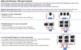
Without getting into the 'why' this page from the paper sumerizes the requirements. (The rest of the paper explains the why)

1609467423352.png
 
Some of the people that would think to install a switch might not think to install a DC-rated switch. An AC-rated switch would likely arc and fail in the closed position.
Yes!! Particularly with the type of current we deal with. The switch must be DC rated to handle both the current and voltage.

The NEC does allow the use of breakers as disconnects, but I don't recommend it.


The NEC actually has a fairly extensive set of requirements around Disconnects. Someday I might do a paper on it.
 
i don’t know why you should need a breaker protection higher than the current measured (or calculated) of your panels shorted.. and as the optimal current is near of the shorted current, that become delicate because between those limits is too near of the optimal current and so, the breaker can be triggered easily..
and why to use breakers on solar panels???

If four panels in parallel and one gets shorted (or bypass diodes fail shorted), the other three dump 3x Isc into the failed one. That could overheat something, so fuse or breaker per panel is required.

You don't want the fuse or breaker to ever trip due to current from the panel, so it is sized at least 1.56x Isc.

As a disconnect, DC breakers are generally more available and lower cost than switches.

I don't know if this fusing of parallel strings has ever protected against an actual failure, or if anything has melted due to such failures without OCP. But it could, if exposed wires were chewed through on a roof.
Arc-fault, on the other hand, has occurred in high-profile cases.

I have high voltage PV strings fused at both ends, because they go to a transformerless inverter - it is not galvanically isolated from the grid. Once you have a piece of electronics connected it is difficult to know it won't backfeed.
 
If four panels in parallel and one gets shorted (or bypass diodes fail shorted), the other three dump 3x Isc into the failed one. That could overheat something, so fuse or breaker per panel is required.

You don't want the fuse or breaker to ever trip due to current from the panel, so it is sized at least 1.56x Isc.

As a disconnect, DC breakers are generally more available and lower cost than switches.

I don't know if this fusing of parallel strings has ever protected against an actual failure, or if anything has melted due to such failures without OCP. But it could, if exposed wires were chewed through on a roof.
Arc-fault, on the other hand, has occurred in high-profile cases.

I have high voltage PV strings fused at both ends, because they go to a transformerless inverter - it is not galvanically isolated from the grid. Once you have a piece of electronics connected it is difficult to know it
i don’t have in mind to protect all things with beakers/switches..
when i want to shutoff/isolate something, i pull the plug..
between the panels and controller, your have at least 2 plugs MC4..

think about that, each cells have a tiny wire connection (which can act as a fuse)..
how a fire can happen here?? (because at 12v, the fire is the only thing you can be fear of)..
a MC4 connections or 30amp wires can melted under what situation with a 400w system?
because the tread here is for 400w and it’s a truly safe and fun project..
 
Flip a switch somewhere to interrupt current flow before unplugging connectors, to avoid burning them. Of course at 17 to 20V less burning than my 380V to 480V.
I shut off AC breaker of my grid-tie inverters, then open DC switches, sometimes touch-safe fuse holders and/or unplug MC and check voltages to make sure I isolated the circuit I meant to work on.

With four, 100W panels in parallel, as you note the voltage is low enough to be safe.
If one panel, its diode, or wiring is shorted, the other three dump current into it. Probably about 6A x 3 = 18A, might barely exceed spec for some wires. Obviously a system with 10 or 20 in parallel would have current high enough it is sure to melt something.

The worst you might see is 300W or 400W dissipated in a couple bypass diodes, which might melt something.

Some panels with insufficient thermal design burn up their diodes in normal operation given full sun and partial shading. It can melt the backsheet and fracture the glass. Probably has a better chance of doing that in a higher voltage series string of panels, more watts available. Single panels in parallel, if one is partly shaded voltage drops below charge controller's voltage and no current goes through the diodes.

With four panels and an MPPT charge controller, I might do 4s1p or 2s2p. That could perform better with partial shading. No need for fuses according to code for use on buildings.

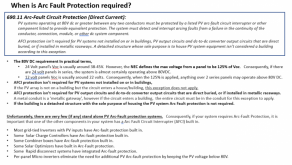
Worth noting that your 400W drops below the threshold for requiring arc-fault or module-level shutdown for residential installations, so you're right it is relatively safe. I probably could design a fault that overheated something, though; that is how I approach these things.
 
Back
Top