grizzzman
Photon Vampire
- Joined
- Sep 21, 2019
- Messages
- 2,757
Have you installed one?It grabs the insulation.
I included a link above to the PDF that shows how to install it.
Have you installed one?It grabs the insulation.
I included a link above to the PDF that shows how to install it.
Shoot i even watched the video and it breezed right over the wire clamp part. Do you have a up close picture of this. Ill be ordering one for my cc asap to try it out.It grabs the insulation.
I included a link above to the PDF that shows how to install it.
I'm quite contempt with my cheap PWMs for now.
I give all wires a "tug" on occasion, the ones i find loose are on my PV/DC breakers from Midnight, those need occasional tightening.
You need to use fine stranded cable on those Victron SCC terminals.
I got a feeling this post might get me some backlash, but I don't know where else to ask.
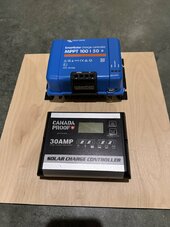
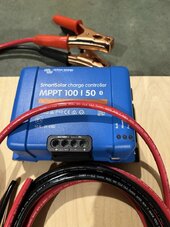
I had recently ordered a Victron 100/20 but had extreme difficulty getting it wired up. The terminal ports on the underneath, regardless of how tight the cables are, always move around and eventually pop out. ... I have attached two photos of the 100/20 and the PWM side-by-side... The ones which Victron (and some Renogy ones) use are giving me great safety concerns.
I got a feeling this post might get me some backlash, but I don't know where else to ask.
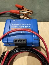
I had recently ordered a Victron 100/20 but had extreme difficulty getting it wired up. The terminal ports on the underneath, regardless of how tight the cables are, always move around and eventually pop out. Now I've been using a rebranded PWM controller for years (and its still in use), but a few here had roasted a previous post I made where I stated the fact I'd prefer staying with PWM over MPPT for their simplicity, despite not being as efficient. I have attached two photos of the 100/20 and the PWM side-by-side; my question is are there any MPPT controllers that use screw/bot terminals? The ones which Victron (and some Renogy ones) use are giving me great safety concerns.
Thanks!


Doesn't seem like it. The kit they offer with a victron controller uses 7 strand pv cables, kinda the opposite of what victron recommends for "high strand"?Doesn’t current connected have an mc4 pigtail connector specifically for this issue

 www.currentconnected.com
Nah, don't leave because of one guy being a dingleberry.I was right in the beginning; backlashed again for a simple question. I'll request this thread be pulled.
In what possible situation is this helpful?I know, user error.Its the terminal screws that are the problem, although I have looked at that item.

Melting the solder = 180 degrees C = wire is too small ? (there are high(er) temperature solders available).No. Solder will wick between wire strands and bind the strands making this connection a fire hazard because solder can melt and loosen the connection. Happened to me once. You should never crimp or compress soldered wire.
You are getting lots of great advice here;
I also have that PWM charger, but do not use it any longer. Note, typically the Victron requires battery voltage plus 5 volts to get the system to start.
View attachment 196180
On the Victron unit;
Don’t use ferrules & use the right fine wire multi strand;
View attachment 196182
The above wire is “Marine Grade” ,,, You can buy it at a local Boat “Marine” Store.
Regarding Backlash ,,, This should never happen, but unfortunately does. The internet can be tough to get thru if you are learning about such things as this, but there are good Members on this Forum that just want to help you out. We all had to learn this stuff from somewhere, as none if us were born knowing it. It is very difficult for inexperienced DIYers knowing who to trust on the internet ,,, I get that. Unfortunately people come with egos & we all have to deal with that stuff. Stick it out & you will learn & have the knowledge. Everything we do comes down to “Knowledge & Motor-skills”. You seem to have a DIY interest ,,, Hang in There it gets easier !!


Soldering wire strands together makes them behave as single strand solid wire but with melting point of solder instead of copper. Solid wire will have sharp contact points inside the terminal block which would run hot due to small contact area. If it gets hot enough to melt the solder the whole connection gets loose and fails burning up.Melting the solder = 180 degrees C = wire is too small?
In your case, a PWM is better. You have prioritize reliability over efficiency. I assume that you have the panels are wired to match the battery voltage (12V battery and nominal 12V panels in parallel). If a PWM controller fails, you can simply connect the incoming solar positive to the battery bank positive to charge the batteries 10 about 14V and disconnect. You are acting as the charge controller. If the panels are wired in series as for use with a MPPT controller, you're dealing with 50V or more; and the current will be a lot lower.Yes. It's for an SUV that frequents rough roads and fields (I supply power for remote workers).
I started to but decided it wasn't need for my install.Have you installed one?
Are we not supposed to help people here? how is ignoring the problem going to help?Nah, don't leave because of one guy being a dingleberry.
In what possible situation is this helpful?
If you feel a response is needed...Are we not supposed to help people here? how is ignoring the problem going to help?
So, pointing out to someone they could have made a mistake is an insult? Oh boy!


