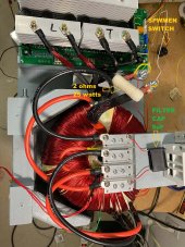
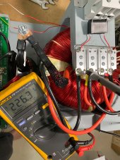
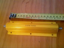
I bought this
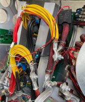
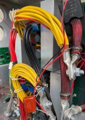
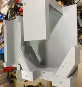
200A inductor for the spwm filter, I don't know how it will perform. I also made a wooden cradle for the toroid and base for the pcb. I hope the cradle will be able to carry the 42 lbs toroid.
Those bright blue Chinese Ferrosilicon Aluminium cores appear to be something quite new that I have never tested myself.
But they seem to have a very soft gradual saturation and a very high flux capacity. which should be ideal for our application.
Results over at The Back Shed with these new blue choke cores look very encouraging.
Now we definitely need the inductance of a series choke to reduce current spikes through the mosfet switching bridge.
The self capacitance of the high voltage secondary winding looks like a dead short at 20 Khz. We can greatly reduce these current spikes with a series choke, and the higher the inductance of the series choke the lower will be the high frequency ripple current and also the inverter idling current.
Inverter idling current is made up of the toroid magnetizing current, plus switching losses mainly due to these nasty high frequency switching spikes. The higher the choke inductance, the happier your switching mosfets will be. And potentially more reliable too.
Putting some impedance between the switching bridge and the toroid can have one unfortunate effect.
This impedance rises with frequency, which is exactly what we want.
Negligible series impedance at 50/60Hz and very high series impedance at the 20Khz switching frequency.
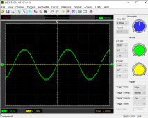
At a few hundred Hz or a very few Khz, the choke impedance can start to become significant, and if our toroid has a self resonance in that range, a harmonic of 50/60Hz can excite ringing in the toroid, and we can get the infamous wobbles, especially under no load.
These harmonics come from harmonic distortion.
The more perfect the pwm sine wave, the lower the harmonic distortion, and resultant harmonics.
Now people experimenting with chokes see these wobbles and assume its caused by a crappy choke.
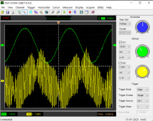
Choke A has no wobbles, choke B wobbles.
So the logical conclusion choke A must be better.
That is the wrong conclusion. Choke B has a higher inductance and series impedance and is definitely the better choke.
So now having a nice big choke and low ripple current, and low idling current, what to do about the wobbles ?
The cure is to lower the self resonance of the toroid.
This also is not intuitive.
If we just slap a capacitor across the secondary we can certainly lower the self resonant frequency, but it then may be tuned to a lower harmonic of 50/60Hz and the wobbles gain in amplitude and look even worse.
But there is a magic solution !
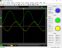
If we tune the toroid to exactly x1.5 the inverter frequency (75Hz or 90Hz) the wobbles will vanish.
We can then run a big efficient choke with all of its advantages without the wobbles that would normally cause.
By tuning the toroid to x1.5 resonant energy cannot build up.
It certainly tries to, but in the following cycle, the resonant build up energy is out of phase, and this self damping action can be very effective.
Tuning needs to be about +/- 1Hz to be really effective and that takes some precision to get right.
Trial and error will not be good enough, you will need to do it properly with a digital frequency counter, a tunable oscillator, and some patience.
This all sounds like voodoo magic, but it does actually work, and its well worth the effort if you have the wobbles problem.
Under more heavy, and especially a reactive load, this toroid self resonance will be de tuned, but the load itself will damp out this ringing.
We need to tune it very precisely under no load, it will then be fine.


")