diy solar

diy solar

Battery cable length - from Lynx distributor

What size were the cables, timselectric? Are we ever going to be told?

It seems like one side is pushing speculation and anecdotal 'evidence' without any recourse to actual figures, and the other is looking at the figures and deciding it isn't going to be a problem.

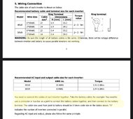
Eggs posted a page from the manual.

I would love to dog pile but I'll be a voice of reason.

1) Why did you ask in the first place?

2) Why didn't the instructions regarding cable length in the manual get followed?

3) Assembly line nature of things would have dictated making 4 equal length cables and not taking up precious milliseconds measure for two different cable lengths.

4) It's a matter of zero consequence because what you're going to do after install is run the system up to redline and check for hot cables and connections. At this time, you can check the voltage at each inverter. If the one with the longer cables has higher voltage drop, you can just call your sparky back and have him make two new cables.

Of all the points where cable length is critical, its there.
 
A heavy duty load test will typically bring variances to the surface whether it is battery cells or power consumption via wires. If you look back at older threads from some of our veteran members even wire length was the common recommendation.

When I run my system on low loads my cells are fairly well balanced. When I hit them hard the runners show up and demonstrate where I need to make corrections.

The advice is based on experience and real life findings.
 
if your cables are not close in length the difference will cause uneven charging/discharging.
The cables being debated are between the busbar and the inverters. The problem with uneven charge/discharge only comes into play with the wires between the batteries and the busbar.
 
I think the better question is, why be too lazy to correct it? It may not cause issue, but it’s also cutting corners which is an overall reflection of one’s work.
Is there a compound effect when dozens of small items are just “good enough”
 
Eggs posted a page from the manual.

I would love to dog pile but I'll be a voice of reason.

1) Why did you ask in the first place?

2) Why didn't the instructions regarding cable length in the manual get followed?

3) Assembly line nature of things would have dictated making 4 equal length cables and not taking up precious milliseconds measure for two different cable lengths.

4) It's a matter of zero consequence because what you're going to do after install is run the system up to redline and check for hot cables and connections. At this time, you can check the voltage at each inverter. If the one with the longer cables has higher voltage drop, you can just call your sparky back and have him make two new cables.

Of all the points where cable length is critical, its there.

Why did I ask in the first place? Because I wanted to know if it would be okay. Timselectric's answer doesn't deal with facts, and doesn't state how bad the 'problem' might be, but insinuates that there IS a problem without explaining why.
I only had 3m or 4m of 70mm2 cable (I can't remember how much I bought now) which I thought would be enough. The instructions in the manual are for 22mm2 cable, as I keep saying over and over, and are not about 70mm2 cable nor are they about cables attached to busbars...
 
One is a Lynx Power In, one is a Lynx Distributor. The Power In will have the three pairs of 25mm2 battery cables from my three Pylontech US5000 batteries.

So obviously in my case I can't use one Lynx Distributor, because I have five pairs of cables in total.

I would have the second Lynx in a different location. You will have cables going everywhere from what I see.


How do you come up with 0.2V? Can you show me an online voltage drop calculator that gives that?
I even used the calculator you have on Rapid Tables to double check. 105A draw (5000W) with 48V nominal, cable 5.6mm, 4 feet round trip 0.178796 volts using the cable size you showed.

There seems to not be a clear answer on cable size, if there is any lettering on the cable take a photo and post it up.

The photo shown in this post is cable much larger than what you have, granted those are 8Kw inverters. But I went to the video for that photo and with the inverters on, it showed one inverter at 50.0V with a 235W load and the other at 49.8V and 135W load. That is very light load, I sure would like to see it under heavy load. In parallel 230V Euro, the loads should be equal on both inverters.

One thing Tim is right about, these are 230V Euro inverters in parallel and one inverter will probably carry more load due to any slight difference in supply voltage. If you watch that video closely, you will see the load on the slave inverter is less than 1/2 of the load on the master, if in parallel it should be equal. This is important as you will hit peak 5Kw output sooner on one inverter under heavy loads and instead of 10Kw, you may only have 7.5Kw load capacity before the inverter with higher load shuts down.
 
Why did I ask in the first place? Because I wanted to know if it would be okay. Timselectric's answer doesn't deal with facts, and doesn't state how bad the 'problem' might be, but insinuates that there IS a problem without explaining why.

He explained exactly why. Now another poster Zwy, has also explained why. You're arguing with experienced people.

You asked because you just wanted to be told that wrong is right so you don't have to do more work. At this point you have said both the manual and Tim's electric (blessed be his eminence) are wrong.

I just told you that its of little consequence right now. You'll know whether it needs correction or not once you run the system up max via load test when it's up and running.

Thats when youll check for hot connections and cables and voltage drops etc.

I only had 3m or 4m of 70mm2 cable (I can't remember how much I bought now) which I thought would be enough. The instructions in the manual are for 22mm2 cable, as I keep saying over and over, and are not about 70mm2 cable nor are they about cables attached to busbars...

So just relax. You'll know if it's an issue or not when you test the system.

We are here to help.
 
I would have the second Lynx in a different location. You will have cables going everywhere from what I see.


I even used the calculator you have on Rapid Tables to double check. 105A draw (5000W) with 48V nominal, cable 5.6mm, 4 feet round trip 0.178796 volts using the cable size you showed.

There seems to not be a clear answer on cable size, if there is any lettering on the cable take a photo and post it up.

The photo shown in this post is cable much larger than what you have, granted those are 8Kw inverters. But I went to the video for that photo and with the inverters on, it showed one inverter at 50.0V with a 235W load and the other at 49.8V and 135W load. That is very light load, I sure would like to see it under heavy load. In parallel 230V Euro, the loads should be equal on both inverters.

One thing Tim is right about, these are 230V Euro inverters in parallel and one inverter will probably carry more load due to any slight difference in supply voltage. If you watch that video closely, you will see the load on the slave inverter is less than 1/2 of the load on the master, if in parallel it should be equal. This is important as you will hit peak 5Kw output sooner on one inverter under heavy loads and instead of 10Kw, you may only have 7.5Kw load capacity before the inverter with higher load shuts down.

This is the cable:


5.94mm diameter.


You can't put the Lynx Power In in a different place, its bus bars literally bolt onto the Lynx Distributor's bus bars, so they have to be side by side.

I didn't notice the load differences on the video, I will have a closer look.
 
"You asked because you just wanted to be told that wrong is right so you don't have to do more work."

More mind readers here. I can easily redo the cables myself in ten minutes if necessary. "so you don't have to do more work". Just unbelievable.
 
"You asked because you just wanted to be told that wrong is right so you don't have to do more work."

More mind readers here. I can easily redo the cables myself in ten minutes if necessary. "so you don't have to do more work". Just unbelievable.
Is that why you spent way more than 10 minutes argueing about it on the internet?
 
They aren't talking about using a busbar in the manual, they are talking about direct connections from a battery or batteries to an inverter or inverters,


So the way I am using the busbars is a different case than what the manual is referring to. I would have thought that Sunshine_Eggo would have known that.
IMG_1458.jpeg

That’s odd

So not only does it talk about bus bars, but also says you’re using the wrong wire size (ya know, since we’re being “technical” now)
 
This is the cable:


5.94mm diameter.

Doesn't compute, the link is for cable 9.4mm in diameter.

You can't put the Lynx Power In in a different place, its bus bars literally bolt onto the Lynx Distributor's bus bars, so they have to be side by side.

You can put the second Lynx anywhere. It only requires cables from one to the other. You do not have to bolt the 2 together. I own a Lynx, I find the busbar sticking out the side to be useless in my application. Maybe I'll add some more batteries and use them but really, I would have just like a bigger enclosure with all terminal connections under it.

I didn't notice the load differences on the video, I will have a closer look.
Look closely, it is all through the video.

The video was made for marketing purposes and not necessarily by a knowledgeable person. As such, technical details such as equal cable length are overlooked. Don't always follow what you see in marketing material, it may not always be correct.
 
I would put the two units close to each other on the left and then hang the power-in over on the right at the same level.

No big deal though, just preference.

Hopefully you at least report to tell us if the cable length causes issues.

How cool is it that Tim's electric knew right away that you were Euro and 230 and thus your units are parallel and that is the exact operating setup where cable length is most critical.

Pretty neat that some random guy here across the pond on an internet forum knew that right away.
@timselectric is an idiot though what are you on about


/sarcasm
 
Last edited:
Is that why you spent way more than 10 minutes argueing about it on the internet?
Does that negate what I just said? We'll see what the result is when it's all set up later this week. I prefer talking about facts, actual figures, not vague 'You might have problems' and the like. Still waiting for timselectric to tell us what size cables he had a problem with on his set up. I wonder why he isn't telling us.
 
One thing Tim is right about, these are 230V Euro inverters in parallel and one inverter will probably carry more load due to any slight difference in supply voltage. If you watch that video closely, you will see the load on the slave inverter is less than 1/2 of the load on the master, if in parallel it should be equal. This is important as you will hit peak 5Kw output sooner on one inverter under heavy loads and instead of 10Kw, you may only have 7.5Kw load capacity before the inverter with higher load shuts down.

Can you give me a timestamp for where you see the loads on the inverters are different?
 
Can you give me a timestamp for where you see the loads on the inverters are different?
Left inverter shows 50.0V in big numbers in the center, he then moves to the right and it shows 49.8V.

It is worse than I thought, at the 1 minute mark, primary is drawing 7A while the slave is drawing 1A.

One has to wonder about why all the jumpy camera work. What are they trying to hide? It isn't that difficult to hold a camera steady, even zoomed in like the video in this post. If I can do it, why can't they instead of producing some vertigo inducing camera work? I will follow along your journey on this one, it might be quite entertaining.
 
Wait how does the 120v loading share on each unit, I thought each carried one leg and the compare the voltage angle to provide 240.

So if you apply a 1500-3000w single phase load on unit, the other is idle, are we saying the battery voltage at one inverter terminal will differ from the other so much they will shut down unless the impedance of each DC connection is absolutely identical?

IMO these set up’s will never have balanced loads between legs each inverter will have different loads and slightly different voltage drops on the leads from the battery.

Or is this whole shut down thing only apply to 240v loads and units sharing properly?
I won't address your questions as I'm on my way out the door but this is Euro 230V, not US/North America 240V split phase.

Inverters are in parallel.
 
Does that negate what I just said? We'll see what the result is when it's all set up later this week. I prefer talking about facts, actual figures, not vague 'You might have problems' and the like. Still waiting for timselectric to tell us what size cables he had a problem with on his set up. I wonder why he isn't telling us.

It's best not to attack Tim's. He delves in the negative side of voltage voodoo.

Also, be aware that your particular inverters are of extremely low quality. They're going to be sensitive to any little thing that comes up.
 
One thing Tim is right about, these are 230V Euro inverters in parallel and one inverter will probably carry more load due to any slight difference in supply voltage.
A few observations.

* The lynx busbar in the system is a common voltage and current point. Differences in current between the busbar and the inverters does not create an imbalance at the battery.... Consequently the question raised by the OP does not involve balance of charge/discharge to the battery.
* A good inverter will coordinate with it's parallel partner to coordinate and balance so they are both driving the same amount of load. (Not all inverters do this)
* Without such coordination, slight variances on the AC wiring can cause noticeable differences in the balance on the AC between the two inverters.
When there are examples of inverters not driving equally, it would be interesting to find out if it is due to differences on the DC side or AC side.
* An inverter will draw the current it needs from the DC to drive what it thinks it needs on the AC side. If the voltage on the DC side is lower, it will draw more current. I guess anything is possible, but It is hard to imagine the DC voltage driving the AC out wattage unless the design of the inverter is really bad. (Note that the inverter has to drive the AC output to the correct voltage and current when the battery is fully charged. (59V) and when the battery is nearly fully discharged (48V) )
* The Victron guide talks about balancing the DC side because the inverter with lower voltage will draw more current, not because it will cause an imbalance in the output. The Victron guide points out that if the difference is large enough one inverter could fault out and ALL of the load would be on the other inverter. (I do not know, but I would bet the Victron inverters coordinate to ensure the inverters are driving equally.)
* If all the lugs, torque, connectors, fuses are identical, the only difference between the two sets of connections in the OPs picture appears to be about about 4 feet of 70mm^2 or 2/0 AWG wire. At 110A this is less than .1V of drop. (The chances are very good that differences in crimps, fuses and connections will cause a larger variance in the DC voltage seen by the inverters than the 4' of wire would)

Even though it is not the popular narrative on this thread, I still don't see an issue with the wiring shown in post #1. The one 'problem' is that if the inverters are running full out, when the batteries get really low the one with the 4' more of wire will kick of slightly before the other one. However, if it got to that, it would not happen very much sooner than if the DC was perfectly balanced. Other than that, I can not come up with an engineering explanation of why it would matter. I have been wrong before and I may be wrong about this, but I don't see it.
 

diy solar

diy solar
Back
Top