diy solar

diy solar

Design Review - Growatt SPF 5000 ES Grid Backup & Neutral Bonding

I think we all can agree that there may be better choices for inverter. Many of them are already UL, so we wouldn't be having any of this conversation. I think we are really just having some enginerding fun solving the david poz conundrum.

I think this is probably going to be the best thing out there - https://www.mppsolar.com/v3/catalogs/LVX6048WP.pdf
This is the one I was thinking I should have got... or at least the non-WP version. But I ordered those EG4 lithium batteries that are supposed to be able to communicate with the Growatt
 
Last edited:
If you have many inductive loads such as multiple motors, Growatt staff recommend the SPF 6000 / 12000T DVM-MPV inverter.
It is special for when there are a lot of electric motors
Directly comes with split phase (two phases and a neutral)
Its disadvantage is its weight and its efficiency compared to the SPF 5000 ES
Next its technical specifications
Thanks, I think the 6000T I looked at had much lower voltage limitations for solar panel?
 
SPF 6000:
  • Not stackable
  • 2x 250VDC MPPT
  • LF Inverter
  • $2,250
SPF 5000ES:
  • 6x Stackable
  • 1x 450VDC MPPT
  • LF Inverter w/ AT
  • $900 + $300 = $1,200 w/ AT
LVX6048WP:
  • 6x Stackable
  • 2x 550VDC MPPT
  • LF Inverter
  • $1,850
Depends on your needs - I'd agree the LVX6048WP is the best choice for arrays <= 7.5kW DC. If you've got a big array, the 5KES scales more cost effectively because you're not duplicating a LF midpoint transformer as you scale the PV MPPTs, and the LVX6048WP isn't available until next year (maybe). I don't think the SPF 6k is very attractive due to not being stackable, being expensive, and having a low voltage MPPT.
 
If you have many inductive loads such as multiple motors, Growatt staff recommend the SPF 6000 / 12000T DVM-MPV inverter.
It is special for when there are a lot of electric motors
Directly comes with split phase (two phases and a neutral)
Its disadvantage is its weight and its efficiency compared to the SPF 5000 ES
Next its technical specifications
I also wanted to add that I think there is better scalability in the GW5kES.
SPF 6000:
  • Not stackable
  • 2x 250VDC MPPT
  • LF Inverter
  • $2,250
SPF 5000ES:
  • 6x Stackable
  • 1x 450VDC MPPT
  • LF Inverter w/ AT
  • $900 + $300 = $1,200 w/ AT
LVX6048WP:
  • 6x Stackable
  • 2x 550VDC MPPT
  • LF Inverter
  • $1,850
Depends on your needs - I'd agree the LVX6048WP is the best choice for arrays <= 7.5kW DC. If you've got a big array, the 5KES scales more cost effectively because you're not duplicating a LF midpoint transformer as you scale the PV MPPTs, and the LVX6048WP isn't available until next year (maybe). I don't think the SPF 6k is very attractive due to not being stackable, being expensive, and having a low voltage MPPT.
I asked Peggy and she said sometime in DEC we should see the LVX6048WP hit the shores.
I think there is one more very attractive feature of that unit, and that would be it's UL listed.

Aside from that 5kES is the best bang for the buck for sure. I have 3 of them so far and plan to take it all the way to 6 to see what these things will do.
 
LVX6048WP:
  • 6x Stackable
  • 2x 550VDC MPPT
  • LF Inverter
  • $1,850
Depends on your needs - I'd agree the LVX6048WP is the best choice for arrays <= 7.5kW DC. If you've got a big array, the 5KES scales more cost effectively because you're not duplicating a LF midpoint transformer as you scale the PV MPPTs, and the LVX6048WP isn't available until next year (maybe). I don't think the SPF 6k is very attractive due to not being stackable, being expensive, and having a low voltage MPPT.
What did you think of the LVX6048 which could be had for $1300 shipped from Taiwan?
Maybe I should get that for the 2nd building.
I'm relying on you guys for the safe Growatt setup since I just realized the seller will charge up to 30% restocking fee to return the Growatt :p
 
What did you think of the LVX6048 which could be had for $1300 shipped from Taiwan?
Maybe I should get that for the 2nd building.
I'm relying on you guys for the safe Growatt setup since I just realized the seller will charge up to 30% restocking fee to return the Growatt :p
We are going to get it figured out for sure. It's a matter of time (because everyone seems to be taking forever to ship parts)

You are looking at that listing on ebay, I would just buy direct from mpp usa -

I would also just wait the few months until the listed model comes out. While it may be a few more dollars and you have to wait a few more months - at least if it explodes into flames you may be able to get some $$$ from your insurance company. Those are my 2C
 
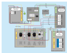
Okay here's the next iteration... changelog:
  • Adds additional contactor to N safety circuit
    • Phases are split across two poles allowing 80A current capacity per phase which is > 63A requirement for 50A upstream CB
  • Adds fast blow fuses to contactor coils
    • 2A for N bonding contactor (expected ~0.6A coil current)
    • 2A for both N safety contactors (expected ~1.2A coil current, this may be undersized but it's better to err on the side of too small here, I think, since it'd be failing-safe/open and disconnecting the Inverter Load Service Panel)
  • Adds neutral and ground buss to Switching Logic Enclosure for better conductor routing
  • Groups conductors between panels with conduit annotations

wiring_with_conductor_annotations.png

Next steps:
  • Conduit annotations need conductors and conduit spec'd in BOM
  • Enclosures need spec'd in BOM
  • Components need BOM
O/T - I'm not sure the LVX6048WP is UL listed. All I see is UL compliant, but I'm not sure that's the same as being listed.
 
Okay here's the next iteration... changelog:
  • Adds additional contactor to N safety circuit
    • Phases are split across two poles allowing 80A current capacity per phase which is > 63A requirement for 50A upstream CB
  • Adds fast blow fuses to contactor coils
    • 2A for N bonding contactor (expected ~0.6A coil current)
    • 2A for both N safety contactors (expected ~1.2A coil current, this may be undersized but it's better to err on the side of too small here, I think, since it'd be failing-safe/open and disconnecting the Inverter Load Service Panel)
  • Adds neutral and ground buss to Switching Logic Enclosure for better conductor routing
  • Groups conductors between panels with conduit annotations

View attachment 71289

Next steps:
  • Conduit annotations need conductors and conduit spec'd in BOM
  • Enclosures need spec'd in BOM
  • Components need BOM
O/T - I'm not sure the LVX6048WP is UL listed. All I see is UL compliant, but I'm not sure that's the same as being listed.
Darn, now I have to source some UL listed fast blow fuses. LOL

I do also have a question about the direct connect between the inverter disconnect service panel and that ground. Can someone explain why that is there and why it would be needed? Won't the ground come through the GW5KES. Also I thought all grounds must be sourced at the supply. Is that not correct?
> I am wrong - see this post
"
Under current NEC rules for new installations there must be an EGC run from the service panel to the subpanel under all conditions.
Note that the important part is that the EGC will provide a low impedance path for fault current back to the POCO service, allowing OCPD to trip quickly, while a local ground rod at the subpanel will rarely be able to serve that purpose."


I am also under the impression that breakers protect the wire from getting hot and causing a fire, so it should be ok so long as the wire size is appropriate for the breaker.

I have some parts trickling in, I am hopeful the conduit connectors show up tomorrow and also my Din rail boxes so we can start getting something done here.
 
Last edited:
Yep - the ground conductor from the Main Service Panel to the Inverter Disconnect Service Panel is simply because calculation of ground fault current can't be done accurately because - if we were to wire the ground through the GW, we don't know the ampacity because it isn't documented. Also, the fewer connections (lugs, terminals, etc) on our grounding conductor, the less chance of something working loose and compromising the fault current needed to trip an OCPD.

It could be argued that we should run two grounds:
  • Main Service Panel --> Inverter Disconnect Service Panel
  • Main Service Panel --> Inverter Load Service Panel
Instead of in the daisy-chain format I have in the diagram, which is:
  • Main Service Panel --> Inverter Disconnect Service Panel
  • Inverter Disconnect Service Panel --> Inverter Load Service Panel
I could definitely be convinced to use the latter of the two approaches if anybody feels that'd be more code-compliant/safe.

As for fault current calculations, that's the next step that needs taken when it comes to conductor ampacity and conduit BOMs. If anybody wants to take a swing at that, please go ahead. Otherwise I'll try this weekend.

I'm also considering extending this wiring diagram to have dual over/under voltage protection relays - one for each leg of the AT. This provides an additional layer of redundancy in our neutral safety circuit.

One thing the most recent design doesn't have is the ability to detect loss of G/N bonding when running in off-grid mode. If anybody has suggestions on detection for this, please say so.
 
I apologize if this is tangent, but y'all are the most technical group of people I can find trying to solve this Growatt 5000 issue. I was wondering if the dangers go away if I just run the 240v well pump from Growatt 5000 inverter, then buy another 2000w 48v 120vac inverter to connect to same Lithium battery bank and supply the booster pump, water softener, and a few lights?
 
I apologize if this is tangent, but y'all are the most technical group of people I can find trying to solve this Growatt 5000 issue. I was wondering if the dangers go away if I just run the 240v well pump from Growatt 5000 inverter, then buy another 2000w 48v 120vac inverter to connect to same Lithium battery bank and supply the booster pump, water softener, and a few lights?
We aim to please :)

Most of what is here is designed to make a split phase system safe with the GW5KES and the SolarEdge Midpoint transformer. I would like to point out that you should always design failsafes into any circuitry that you care about. These are essentially long lived small scale power stations, and if you look at any POCO you would find that they have plenty of monitoring circuits to ensure what they are doing is safe. I would rather have an over engineered system that will trip at the first sign of failure than one that burns up my $3k well pump or $10K A/C. Many are willing to take a risk and that is ok, so long as the risks are understood.

I design large scale systems (NOT ELECTRICAL) for a living, so being technical and checking all the common sense boxes makes sense to me.

So if you are to go that route, you will need a to swap the PV to which one you want to charge the battery bank. You will also need a battery bank that supports RS485.

I asked signature solar this exact question and here is what they said.
>>>
I bought two 5kW Stackable 48V Growatt inverters last night (along with other things) to support my needs for 240V. I was thinking it would be easier to manage separate 120V and 240V panels over the long term.
Can a battery pack be wired in to the 5K Growatt and say a 12K 120v Growatt at the same time? Same for the Solar Array.
>> From Mike
Yeah you can have the inverters tied to the same battery pack. They just need to communicate to each other over the RS485 cable and the AC must be completely isolated as you said below.

The PV can’t be connected to them at the same time. The MPPT controllers would be competing for control. If you switch the PV array with a PV switch that would work.
>>>

(Mike, if you are reading this, thank you for taking the time to answer my questions. )

Hope that helps @lns
 
Yep - the ground conductor from the Main Service Panel to the Inverter Disconnect Service Panel is simply because calculation of ground fault current can't be done accurately because - if we were to wire the ground through the GW, we don't know the ampacity because it isn't documented. Also, the fewer connections (lugs, terminals, etc) on our grounding conductor, the less chance of something working loose and compromising the fault current needed to trip an OCPD.

It could be argued that we should run two grounds:
  • Main Service Panel --> Inverter Disconnect Service Panel
  • Main Service Panel --> Inverter Load Service Panel
Instead of in the daisy-chain format I have in the diagram, which is:
  • Main Service Panel --> Inverter Disconnect Service Panel
  • Inverter Disconnect Service Panel --> Inverter Load Service Panel
I could definitely be convinced to use the latter of the two approaches if anybody feels that'd be more code-compliant/safe.

As for fault current calculations, that's the next step that needs taken when it comes to conductor ampacity and conduit BOMs. If anybody wants to take a swing at that, please go ahead. Otherwise I'll try this weekend.

I'm also considering extending this wiring diagram to have dual over/under voltage protection relays - one for each leg of the AT. This provides an additional layer of redundancy in our neutral safety circuit.

One thing the most recent design doesn't have is the ability to detect loss of G/N bonding when running in off-grid mode. If anybody has suggestions on detection for this, please say so.
Can't we just put GFCI breakers on the outputs to handle that? It should trip if there is a break in the off grid G/N bond? I will have to test that theory, but I think that would fit the bill same as it does in a service entrance load center.


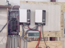
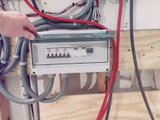
Also I had some parts start coming in, so I figured I would share some photos for the purpose of direct criticism. I know the wiring for the batteries needs some help, but the rest isn't coming out too bad. The third breaker will be tied to the inverter I have been too busy to head down to signature solar to pick up. I also need to pop some of those spacers out of the DIN box so I can fit the second voltage monitor into.

Side note: Anyone know how to do a ground bar in a box like this?

IMG_20211105_204156.jpg
IMG_20211105_204148.jpg
 
Last edited:
Looks great! Really cool to see the design coming together. If you've got a notepad, it'd be great to get conductor gauges & types you're using for everything. I'd be curious to hear your source for battery cables/lugs as well if you've got it handy. I'll try to get a BOM together this weekend.

Re: GFCI - you're right that a single pole GFCI CB on a 120V load in the Inverter Load Service Panel would (should) trip if we lost our G/N bond and had a fault to ground. But it'd have to be a GFCI breaker. I believe a non-GFCI ground fault (with loss of G/N bond) wouldn't trip the OCPD and we'd have 120V on grounded device surfaces. Not sure if we could move the GFCI breaker up to the 50A 2P CB in the Inverter Disconnect Service Panel in an effort to protect all branch circuits on our Inverter Load Service Panel - I'll think about that one.

For bussing operations on a DIN setup, you can use a power distribution block or terminal block. The distribution block is literally just a hunk of metal with terminal connections drilled into it (all inputs/outputs bonded and unfused), and the terminal block is normally a 1:1 input:eek:utput, but can also be paralleled with a bussing bar and screws. I'm not 100% sure a) the physical dimensions/standards and b) the current capacity associated with terminal block bussing. If neither of those tickle your fancy, you can just find a spot to stick a standard neutral bar which is available at any home center.
 
Not to totally derail things, but have you seen this before? It does completely solve the ground / neutral bonding problem in a UL listed way. Turns the solar system into a full SDS, and may be more inline with what an inspection might be looking for. Portable Gensets aren’t UL listed that I know of, and this would make the non UL solar function the same way as a portable genset/SDS (separately derived system -
).


It is manual but would allow us to connect to regular mains service and solar/gen service as a full SDS. It completely solves the neutral ground bonding issue and allow you to select which load hit solar whenever you want. It does make things less complex with the contractors, but it also isn’t free either. Using this allows one to use a genset as the A/C input for the inverter, and then select which load hits solar or POCO services.

Just a though for those who want to use their solar as backup emergency power.
 
Last edited:
Looks great! Really cool to see the design coming together. If you've got a notepad, it'd be great to get conductor gauges & types you're using for everything. I'd be curious to hear your source for battery cables/lugs as well if you've got it handy. I'll try to get a BOM together this weekend.

Re: GFCI - you're right that a single pole GFCI CB on a 120V load in the Inverter Load Service Panel would (should) trip if we lost our G/N bond and had a fault to ground. But it'd have to be a GFCI breaker. I believe a non-GFCI ground fault (with loss of G/N bond) wouldn't trip the OCPD and we'd have 120V on grounded device surfaces. Not sure if we could move the GFCI breaker up to the 50A 2P CB in the Inverter Disconnect Service Panel in an effort to protect all branch circuits on our Inverter Load Service Panel - I'll think about that one.

For bussing operations on a DIN setup, you can use a power distribution block or terminal block. The distribution block is literally just a hunk of metal with terminal connections drilled into it (all inputs/outputs bonded and unfused), and the terminal block is normally a 1:1 input:eek:utput, but can also be paralleled with a bussing bar and screws. I'm not 100% sure a) the physical dimensions/standards and b) the current capacity associated with terminal block bussing. If neither of those tickle your fancy, you can just find a spot to stick a standard neutral bar which is available at any home center.
I am using 6 gauge for all A/C side wiring, because Lowe’s didn’t have anything else. Had to buy a whole spool.

The contactors in use here ARE NOT going to stay, they are stand ins while I wait on my listed ones to show up sometime in.....whenever they finally get here.

I saw some 50 amp gfci breakers at Lowe’s, I think they are used for a hot tub. The disconnect panel is where I imagined it would go so it could protect downstream branch circuit. I will need to research more though to see if that would in fact handle the fault properly or it would cost money people don’t need to spend.


I got the welding cable on amazon (made in the USA at that!), even comes with really nice lugs.

 
Last edited:
So if you are to go that route, you will need a to swap the PV to which one you want to charge the battery bank. You will also need a battery bank that supports RS485.
oh, I was not thinking about 2 All-in-one units, but 1 Growatt 5000es to charge/inverter for 240v and 1 standalone inverter for 120v loads connected to same 48v battery. Is there still need for communications between an all-in-one and a standalone inverter?

downside I can see is that the 120v load won't benefit from the Solar and the Utility powers that the Growatt 240v loads would get?
 
Last edited:
oh, I was not thinking about 2 All-in-one units, but 1 Growatt 5000es to charge/inverter for 240v and 1 standalone inverter for 120v loads connected to same 48v battery. Is there still need for communications between an all-in-one and a standalone inverter?
So you are saying the 120V inverter would only be inverting? I guess that would probably work, but I fear there may be devils in those details for how to set it up.

Maybe post up some parts you were thinking about and we can noodle on it.
 
For what it’s worth once we get the OP’s question worked out, I planned to also show how to do this with a genset input on the GW5KES and tie back to the main panel with a simple interlock. I also wanted to show people how to setup this system as an SDS so it could be used as a backup (or primary) power source with manual load shedding. Auto load shedding is a very expensive experiment, otherwise I would demo that too.

I vote this be the GW5KES mega thread. Maybe we can convince someone to give it a pin so it sticks around for a while.
 
I was trying to get this very question answered by the people at Signature Solar just this past week. The person I emailed back and forth with was unhelpful and never answered my question about how to wire AC in for the on-grid scenario.
I got that too from awhile back when one of Will's youtube lessons pointed at this newer all in one. I like some of the improved specs over some other GroWatt models, but would rather have 120vac or 240vac split phase (usa standard) directly from the all in one itself, instead of 240vac single phase (European n Asian standards). I do not get why GroWatt's data sheet does not clearly state (on some I have looked at ...) 240vac "single phase"; Plus I have not yet seen clear info and diagrams on what is require for convertion to 240vac usa style "split phase".
 
Signature Solar is probably hesitant to give advice to unlicensed electricians for fear of litigation. They can't control the end state installation.

The question should be focused on the Solar Edge transformer and its designed connection to a Solar Edge inverter.
The baseline question, does the Solar Edge inverter switch all three poles of the transformer when it switches over to inverter power?
 
Back
Top