danphillips
New Member
- Joined
- Oct 29, 2019
- Messages
- 108
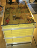
Is anyone interested in aluminum supports as in the attached picture. I have access to a fabricator that can cut custom sizes of 1/4 inch aluminum sheet. I haven't checked on price yet but if there is enough interest let me know the dimensions and I'll get some pricing.

")