


You are using an out of date browser. It may not display this or other websites correctly.
You should upgrade or use an alternative browser.
You should upgrade or use an alternative browser.
Hey all
- Thread starter Noflers
- Start date
Make sure the 4 gauge wire fits in your solar charge controller. My Victron spec sheet says 6 gauge max. It was pretty close with 6 gauge. If your controller has studs for ring terminals then nevermind.
4 gauge wire for panels to SCC is crazy.I think I have a better idea of what I need now. The only thing I forgot to add to the cart is the 4 gauge wire to go from the junction of all the panels to the SCC.
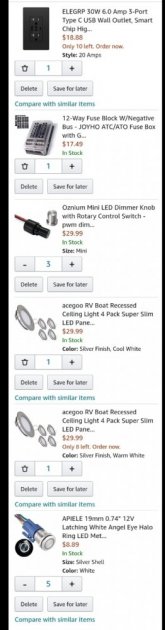
To break it all down:
1. 8awg wire for between the 4 to 1 branch connectors and junction.
2. Power distribution block (need to add one more).
3. 1500W inverter.
4. Epever 40A controller.
5. Crimp connectors for various 12V needs.
6. 4 to 1 branch connectors.
7. Inline fuses for between the panels and branch connectors. (Still need to find 7A fuses)
8. 2 to 1 branch connectors (need to remove)
9. USB socket.
10. Inverter cables.
11. Circuit breaker for between battery and inverter.
12. Bus bars for 12V power distribution. Thinking 10g wire to the bus bar from the fuse block, then 14g wire to the different light circuits.
You must be using a 12V amperage chart to miscalculate that.
4 AWG???? Lucky that you forgot to buy them.I think I have a better idea of what I need now. The only thing I forgot to add to the cart is the 4 gauge wire to go from the junction of all the panels to the SCC.
To break it all down:
1. 8awg wire for between the 4 to 1 branch connectors and junction.
2. Power distribution block (need to add one more).
3. 1500W inverter.
4. Epever 40A controller.
5. Crimp connectors for various 12V needs.
6. 4 to 1 branch connectors.
7. Inline fuses for between the panels and branch connectors. (Still need to find 7A fuses)
8. 2 to 1 branch connectors (need to remove)
9. USB socket.
10. Inverter cables.
11. Circuit breaker for between battery and inverter.
12. Bus bars for 12V power distribution. Thinking 10g wire to the bus bar from the fuse block, then 14g wire to the different light circuits.
2S4P 100 watt panels
37Vmp
21.6A Imp
15 feet one way on a camper?
Only needs 10 AWG for about 2% voltage drop.
You can change the inputs on this calculator.
Voltage Drop Calculator
This free voltage drop calculator estimates the voltage drop of an electrical circuit based on the wire size, distance, and anticipated load current.
Noflers
New Member
- Joined
- Jan 24, 2021
- Messages
- 39
Good catch, I checked and 6 gauge is the biggest that can fit.Make sure the 4 gauge wire fits in your solar charge controller. My Victron spec sheet says 6 gauge max. It was pretty close with 6 gauge. If your controller has studs for ring terminals then nevermind.
Noflers
New Member
- Joined
- Jan 24, 2021
- Messages
- 39
4 AWG???? Lucky that you forgot to buy them.
2S4P 100 watt panels
37Vmp
21.6A Imp
15 feet one way on a camper?
Only needs 10 AWG for about 2% voltage drop.
You can change the inputs on this calculator.
Voltage Drop Calculator
This free voltage drop calculator estimates the voltage drop of an electrical circuit based on the wire size, distance, and anticipated load current.www.calculator.net
Except I've decided on 12V... Forgot to mention. Stop at 46.8A, is 4-6 gauge still over kill?
Noflers
New Member
- Joined
- Jan 24, 2021
- Messages
- 39
Looks like I'll be skipping the junction and running 6 or 8 gauge from the panels.
I both apologize for my hard head, and thank you for your help. I'm trying my best to get this all crammed in my brain.
I was still figuring my wire size by adding the amps and only using 12V for the voltage.Also, I was using 186A and I'm not sure how I got that...
I both apologize for my hard head, and thank you for your help. I'm trying my best to get this all crammed in my brain.
I was still figuring my wire size by adding the amps and only using 12V for the voltage.Also, I was using 186A and I'm not sure how I got that...
12V battery?Except I've decided on 12V... Forgot to mention. Stop at 46.8A, is 4-6 gauge still over kill?
Are your 100w panels wired 2S4P?
How do you get 46.8A?
If so then your 12V battery has nothing to do with the volts and amps flowing from your panels to your SCC and the gauge of the wires.
An MPPT has 2 sides.
The Input from panels and the Output to charge whatever voltage battery.
And what watts is them panels??The specs of the panels I want to buy... they will be wired in paralell
Isc: 5.86A X 8 = 46.8A
So im thinking 6-8 gauge between the panels and SCC, and the same from the SCC to battery
100w like you already posted??
Why did you change from 2S4P to 8P?
Noflers
New Member
- Joined
- Jan 24, 2021
- Messages
- 39
2s4p was only a consideration when I was confused about my options for an SCC. I thought I would need more controller that I would actually need. So I thought for a sec about going with a 24V system.
But that's cleared up now. And I'm back to my original 12V plan. 800W panels, and a 40A controller.
But that's cleared up now. And I'm back to my original 12V plan. 800W panels, and a 40A controller.
800w panels even at 14V needs 57A.2s4p was only a consideration when I was confused about my options for an SCC. I thought I would need more controller that I would actually need. So I thought for a sec about going with a 24V system.
But that's cleared up now. And I'm back to my original 12V plan. 800W panels, and a 40A controller.
40A x 14V is only 560 watts out of your 800 so you are over panelled
Wiring 2S4P or 8P has not much to do with battery voltage.
Noflers
New Member
- Joined
- Jan 24, 2021
- Messages
- 39
Ahhh, I see. I thought you would only series connect panels if you were running a 24V+ system...800w panels even at 14V needs 57A.
40A x 14V is only 560 watts out of your 800 so you are over panelled
Wiring 2S4P or 8P has not much to do with battery voltage.
What brand and model is your SCC?2s4p was only a consideration when I was confused about my options for an SCC. I thought I would need more controller that I would actually need. So I thought for a sec about going with a 24V system.
But that's cleared up now. And I'm back to my original 12V plan. 800W panels, and a 40A controller.
Noflers
New Member
- Joined
- Jan 24, 2021
- Messages
- 39
Epever 40A MPPT is the plan. https://www.amazon.com/gp/aw/d/B07K9HBYPY/ref=ox_sc_act_image_4?smid=A2P9F29Y7BYBUO&psc=1

Hedges
I See Electromagnetic Fields!
- Joined
- Mar 28, 2020
- Messages
- 20,791
Reason I'm having trouble deciding is because 8 panels will make a max of 180.8V ... And the 80A controller can handle 200V max.
180.8V would be too much for a 200V controller.
Panel spec are given at 25 degrees C, and if you visit a freezing area the Voc could increase 15%
Look up temperature coefficient on data sheet (or use a conservative assumption) and calculate adjusted Voc for historical record cold temperature.
(your most recent diagram doesn't look like many panels in series, but double-check whatever you plan to build. And check actual voltage with DMM before connecting to SCC.)
Hedges
I See Electromagnetic Fields!
- Joined
- Mar 28, 2020
- Messages
- 20,791
Is your system meant to be positive ground?
Four strings of PV panels in parallel, ought to be individually fused. MC4 fuses are one way to go. Four individual wires to circuit breakers is another, doubles as PV array disconnect shown as [2] in your picture. With (polarized) breakers, I favor ganging them to operate together by sliding a stiff wire through the hole in their handles (my safety upgrade because I dispute manufacturer's assertions.)
Suggest quality fuse on battery. Your planned breakers probably don't have AIC rating sufficient to interrupt the short-circuit current lithium battery can deliver. I calculate 20,000A (haven't seen a value from manufacturer or test result), and a class-T fuse is rated for that.
I would use something like 250A class T fuse (regardless of whether that exceeds ampacity of wires) and rely on breaker working in case of overload. Fuse should never blow, but in case of a short circuit it will clear faster than breaker.
1000W inverter is nominally 80A at 12V, a bit more for inefficiency. So 200A breaker is probably higher than required. It is OK if wires can handle that. Midnight has a 175A breaker with high ratings. That could be put right at battery (interrupting not just inverter but everything else too) and could be used in place of the class T fuse I suggested (that 175A breaker is rated 50kA interrupting)
Diagram is 2S4P so only 45Voc so plenty of room for really cold temps even on a 100V max input SCC.180.8V would be too much for a 200V controller.
Panel spec are given at 25 degrees C, and if you visit a freezing area the Voc could increase 15%
Look up temperature coefficient on data sheet (or use a conservative assumption) and calculate adjusted Voc for historical record cold temperature.
(your most recent diagram doesn't look like many panels in series, but double-check whatever you plan to build. And check actual voltage with DMM before connecting to SCC.)
Nowhere on your diagram does it say 12V battery or inverter.
You say Lishen which is irrelevant but omit voltage.
8 x 100 watts panels is 800w on a 40A SCC into a 12V battery?
14V x 40A is only 560 watts so you are leaving a lot of wattage on the table.
Similar threads
- Replies
- 86
- Views
- 3K
- Replies
- 33
- Views
- 2K