diy solar

diy solar

Install and Operation of the SUNGOLD 10KW 48V SPLIT PHASE SOLAR INVERTER

I know, I know....I'm keeping an eagle eye on it. The crimp connectors didn't want to work on that big wire so I resorted to those large twist-on's.

Definitely not a recommended procedure.

P.S. you got an eagle eye Mr. @42OhmsPA ! :)

and yes that's the same 14 AWG I had connected to the plug for the Dryer. and also I'm not running my entire house off of this just the 5 circuits with a max load of maybe 1 Kw at any given time. I think it's safe until I get a real electrician in and run wires and all that ... probably when I replace my breaker box and get it all squared away for solar and heat pumps and up to code and all that....just before I go legit with my panels on the roof. :unsure::giggle::cool:
 
Nothing wrong with wire nuts if they are appropriately used to the manufacturer specifications. Millions probably billions have been used in the field. Now for the flying splice that's a different story!????
 
Nothing wrong with wire nuts if they are appropriately used to the manufacturer specifications. Millions probably billions have been used in the field. Now for the flying splice that's a different story!????

Can you say "Junction Box" ... yeah I thought you could. ?:LOL::ROFLMAO:

And now I have a name for that! Thank you!

If splices had wings
we'd all be angels!

Yes!
 
Last edited:
BTW I'm more worried about the sewer backing up, which it has done in that room and getting into my batteries than electrical connections.

The batteries are the most expensive part of my system.

I do have a rack ordered. :)
 
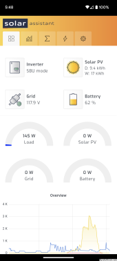
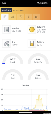
The idle consumption of the inverter is ~100w (I clamped it twice).
The BMS's likely don't read low current (under 1a).

This is why a quality shunt is recommended as your go to for verification.

Ps - it appears the option to program idle consumption is no longer available in the latest builds of SA, so I apologize for sending you on a goose chase earlier.
No problem.....appreciate the help.

What's strange is that I didn't see this behavior until I installed the three additional batteries. With just the two initial batteries everything seemed to match up and add up and even out...but not now. :)
 
No problem.....appreciate the help.

What's strange is that I didn't see this behavior until I installed the three additional batteries. With just the two initial batteries everything seemed to match up and add up and even out...but not now. :)
That would be because the additional batteries reduce the current going through each BMS...
150w / 2 batteries = 75w per battery
75w / 51v = 1.47a per battery.

150w / 5 batteries = 30w per battery
30w / 51v = 0.588a per battery...

Isn't solar and energy storage fun ?
 
That would be because the additional batteries reduce the current going through each BMS...
150w / 2 batteries = 75w per battery
75w / 51v = 1.47a per battery.

150w / 5 batteries = 30w per battery
30w / 51v = 0.588a per battery...

Isn't solar and energy storage fun ?
Not sure I understand what you are saying, but gotta be something like that I'm thinking.

It's not like energy is disappearing, the opposite thing happens when PV is flowing in.... reading is less on the battery such that the battery watts in + the load watts is less than the PV incoming watts.
 
Just got a message from Sungold...looks like my battery - rs232 cable is on the way via USPS.

The next thing I'm wondering...even if it works....is if Windows requires special FTDI drivers for this cable/comm/connection will it even work with the Raspberry Pi?
 
I'll be damned! The Current Connected Cable WORKED!!! I can see the battery information!

(at least with my laptop! will try with Pi shortly!)

 
Please publish a wiring diagram of cable! And block diagram of inverter and battery connctions.
 
Please publish a wiring diagram of cable! And block diagram of inverter and battery connctions.
I'm not taking it apart or f'n it up just to get that. I'm just ecstatic that it is working....

I also have faith now that the Sungold cable will work because the key, the secret is the DB9 -> RJ11 rs232 half of the cable

I tried my other FTDI USB -> DB9s with the Current Connected DB9-> RJ11 rs232 and they ALL work....

but the other DB9->Rj11 will not work with any of them.

This leads me to believe that Sungold (as I suggested earlier) has changed the pinouts of the RJ11 (or that the Pace BMS did it dunno)

In any case I'm Thrilled and glad to find the solution and share it here!

Woo-Hoo!
 
The setup is standard.... Sungold 10K with Sungold batteries in Parallell
the battery monitoring cable is the one mentioned above from Current Connected
FTDI Usb -> Db9 and DB9->Rj11 plugged into the RS232 port on Battery # 1
 
Examine through transparent plugs, write up a chart of colors.
Or insert in RJ45 jacks and buzz them out.
Note which end of cable in diagram or table goes where.

This would let others fabricate their own, but simply cutting a patch cord in half and splicing.
 
Examine through transparent plugs, write up a chart of colors.
Or insert in RJ45 jacks and buzz them out.
Note which end of cable in diagram or table goes where.

This would let others fabricate their own, but simply cutting a patch cord in half and splicing.

Okay....was a bit difficult cause they had silicon gobbed all over the db9 internals but here's the wiring for the DB9 -> Rj11

The DB9 is female the RJ11 is male/plug

DB9 - RJ11
pin5 - pin5 (black)
pin3 - pin4 (red)
pin2 - pin3 (green)

(yellow Not Connected R11 pin 2)

IMPORTANT - Please Note that I edited this! I had the pin numbers wrong when first posted. Should be correct now!
(these male/female/pin numbers etc are quite confusable! And I'm easily confused!)
 
Last edited:

diy solar

diy solar
Back
Top