diy solar

diy solar

Install and Operation of the SUNGOLD 10KW 48V SPLIT PHASE SOLAR INVERTER

@42OhmsPA

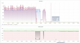
So my wife woke me up at about 6:40AM this morning and said, "The lights are flashing".
I went and looked at the inverter and it was clicking back and forth from batts to grid, it would click to grid then 'trip' back to batts. There was 0 volts from PV. I started turning off loads from the inverter and it stopped and went to utilities. I slowly added loads back to the inverter and it was fine until I reached, "Shed Power" which is a buried underground line to my shed. It also started doing it again, when I turned on "Living Room Light = Microwave Out". I couldn't tell if it was shed specifically causing it or a combination of multiple circuits on.

We did get a lot of rain this morning, the most since shed has been added to the panel.

I am theorizing I have a bad ground on the line to the shed? I am not sure where to start here. I know my wife woke up at 6AM and started getting ready for work. I was in SOL mode with 35% left on my batteries.

I ask her what she did this morning, she said she used the microwave, that's about it.

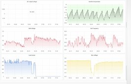
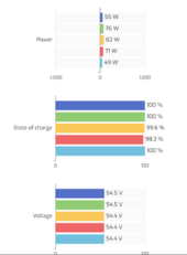
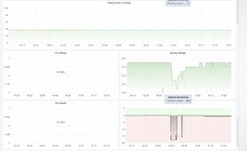
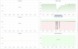
Curious if you guys see anything in my graphs that may indicate what happened. I have nothing on the inverter right now until I can be home with it to see what happens.
A.JPGB.JPGC.JPGD.JPG
 
Last edited:
Well at least though the power needs during the day can come from the panels while the batteries sit in reserve.

P.S. those dang microwave ovens suck a lot of current!
 
I started to panic about the forecast 7 days lack of sunshine and ran 8AWG from a - unfortunately far away - subpanel to the SGP.. and it works great. The meaning of setting [28] .. trial and error.

Of course as I finished, the sun came out in full force.

But I will sleep better now.

20240205_133723.jpg
 
I started to panic about the forecast 7 days lack of sunshine and ran 8AWG from a - unfortunately far away - subpanel to the SGP.. and it works great. The meaning of setting [28] .. trial and error.

Of course as I finished, the sun came out in full force.

But I will sleep better now.

View attachment 193646
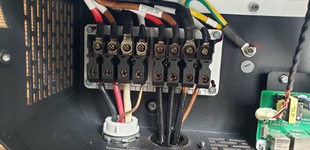
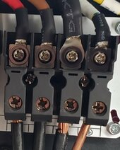
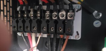
Am I seeing things or do the washers / terminals on the right look like they got hot?
Screenshot_20240205-175359.jpg
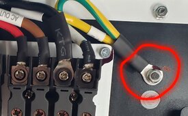
Is it correct that N and G are bonded in the photo? Should I connect that screw to a copper rod into the ground?
Where do you see a NG bond?
 
the washers / terminals on the right look like they got hot?

I think they got hot on 1/12/24 at 2:14pm
The wiring in my main panel is a desaster, as I see it. I actually made a separate thread about it here:

TLDR: most circuits in my main panel don't have a dedicated ground, as there are multiple grounding spots inside the main house. Also, several circuits share neutrals. So it has been difficult to move circuits over to my offgrid panel.

I conducted a test on one circuit that was on my offgrid panel: created a short at a grounded outlet by putting solid copper wire from hot to neutral.

The associated 15A GE breaker did not trip :-(
But the inverter threw alarm 0x0011 (short circuit protection). Must have been very high amps.

The outlet in this test has a ground wire hooked up, I just don't know where it goes to.

I had not noticed the dark spots.

Where do you see a NG bond?

Isn't this one?
20240205_154050.jpg


So, now that I have the inverter connected via AC in to the main, I should separate these 2 and no longer need to worry about a ground rod?
 
I think they got hot on 1/12/24 at 2:14pm
The wiring in my main panel is a desaster, as I see it. I actually made a separate thread about it here:

TLDR: most circuits in my main panel don't have a dedicated ground, as there are multiple grounding spots inside the main house. Also, several circuits share neutrals. So it has been difficult to move circuits over to my offgrid panel.

I conducted a test on one circuit that was on my offgrid panel: created a short at a grounded outlet by putting solid copper wire from hot to neutral.

The associated 15A GE breaker did not trip :-(
But the inverter threw alarm 0x0011 (short circuit protection). Must have been very high amps.

The outlet in this test has a ground wire hooked up, I just don't know where it goes to.

I had not noticed the dark spots.


Isn't this one?
View attachment 193667


So, now that I have the inverter connected via AC in to the main, I should separate these 2 and no longer need to worry about a ground rod?
No, that is only for 'special circumstances to make the inverter the N-G Bonding point.
The N-G bonding should be in your main panel, but as you said there are numerous places where that is violated in your house. (same here I believe, but hasn't been a problem)
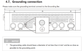
There's this in the manual, but again I think that grounding is only for special conditions otherwise you can cause ground loops.

Screenshot 2024-02-05 170046.png
 
Last edited:
I think they got hot on 1/12/24 at 2:14pm
The wiring in my main panel is a desaster, as I see it. I actually made a separate thread about it here:

TLDR: most circuits in my main panel don't have a dedicated ground, as there are multiple grounding spots inside the main house. Also, several circuits share neutrals. So it has been difficult to move circuits over to my offgrid panel.

I conducted a test on one circuit that was on my offgrid panel: created a short at a grounded outlet by putting solid copper wire from hot to neutral.

The associated 15A GE breaker did not trip :-(
But the inverter threw alarm 0x0011 (short circuit protection). Must have been very high amps.

The outlet in this test has a ground wire hooked up, I just don't know where it goes to.

I had not noticed the dark spots.
Wow. I get you can't wait to get more circuits rewired to the inverter.
If you trace them back they should go to the grounds for the AC.
There is a setting for N/G bonding in the menu. I've left it alone.
So, now that I have the inverter connected via AC in to the main, I should separate these 2
No, I wouldn't.
and no longer need to worry about a ground rod?
You should have one main ground rod for the house that everything runs back to.
 
washers / terminals on the right look like they got hot

Disclaimer: I hope "Cindy" doesn't find this. In case I ever have a warranty claim.

Well, I already spilled the beans about my questionable installation and that probably less than professional test with the Hot-to-Neutral wire..

But when photographed from the side, the terminals look normal.

It wouldn't have made sense that the G got hot. Nothing is hooked up to it.

The question remains. Why did the breaker not trip? Is it that the inverter is just so much faster than the breaker?

20240205_171418.jpg
 
Disclaimer: I hope "Cindy" doesn't find this. In case I ever have a warranty claim.

Well, I already spilled the beans about my questionable installation and that probably less than professional test with the Hot-to-Neutral wire..

But when photographed from the side, the terminals look normal.

It wouldn't have made sense that the G got hot. Nothing is hooked up to it.

The question remains. Why did the breaker not trip? Is it that the inverter is just so much faster than the breaker?

View attachment 193700
That photo looks much better, must have been the angle.

To the best of my knowledge breakers aren't designed to trip instantly unless there's a metric f ton of current flowing, even then there would be a slight delay, look at trip curves for a few different ones.

The inverter is using relays and likely other things I don't understand completely that operate in milliseconds when a fault is detected.
 
Disclaimer: I hope "Cindy" doesn't find this. In case I ever have a warranty claim.

Well, I already spilled the beans about my questionable installation and that probably less than professional test with the Hot-to-Neutral wire..

But when photographed from the side, the terminals look normal.

It wouldn't have made sense that the G got hot. Nothing is hooked up to it.

The question remains. Why did the breaker not trip? Is it that the inverter is just so much faster than the breaker?

View attachment 193700
Yep. The inverter electronics are much much much faster than a breaker!
 
All acting way too normal the last few weeks. I'm loving it!

Should be getting my January Xcel bill in the next few days. Expecting about the same as last month. Saving about 50% on the electric.


Screenshot 2024-02-06 142200.png
 
Mine are finally happy too now that they've seen some sun. (I need to drop my float voltage a bit now that they are starting to balance).
Screenshot_20240206-162632.jpg
 
Had some great sunshine today, battery was full by 11:30am (25kWh). What a waste. Secondary system (15kWh) and PHEV also full. And then power outage. Looking really good now to buy this system in November. This outage will take time.. it started 5h ago and they have not even sent anyone to inspect what's wrong. I expect 72h. Weird that such nice weather can cause outages.
 
so here is a question for the veterans of AC-in charging (@Kenny_, @42OhmsPA )
I was able to charge yesterday morning from the utility up to 90% or so, at that point I shut off and let the sun complete the job. It was just a test.
A few hours later the power went out, and with the water heater now installed (80G, uses 4500W) and less than an hour of sunshine today, I removed the grid connection and hooked up a gas generator to AC-in. [01] is set to "UTI". It charged to about 83% SOC at which point I noticed the generator running less noisy. Sure enough the battery was discharging. The contacts at AC-in measure 240V between L1 and L2, and 120 on L1-N and 120 on L2-N. I hear a relais clicking. The AC-in breaker is in the "on" position. The inverter just won't accept power from the generator any more. I waited a few hours to bring the SOC down .. right now it's at 80%, and it does not accept power.
[04] is at 49.2V but this should not matter in UTI, right?
[28] was initially at 80A and I increased it to 120A to make more use of the generator. The inverter stopped accepting power about 10 minutes after I increased [28] from 80 to 120A. It's now back to 80 and it's not helping either.

No alarms thrown.

Not sure what to show.
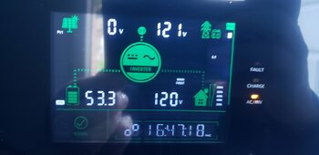
This picture shows 121V from the generator but power flows from battery to the house.

20240207_164858.jpg
 
Do you have comms enabled?
The inverter / BMS will start slowing the charging as it approaches full I've seen.

Also depending on the power in the inverter might not like your generator. I don't have experience with that... but @Lighthouse Beacon I think has had some issues with dirty AC in...


Oh also ... Once charging stops it will not restart until you hit the bottom params (other than from solar/pv)

..you could force it by changing the inverter params but I haven't tried that....
 
so here is a question for the veterans of AC-in charging (@Kenny_, @42OhmsPA )
I was able to charge yesterday morning from the utility up to 90% or so, at that point I shut off and let the sun complete the job. It was just a test.
A few hours later the power went out, and with the water heater now installed (80G, uses 4500W) and less than an hour of sunshine today, I removed the grid connection and hooked up a gas generator to AC-in. [01] is set to "UTI". It charged to about 83% SOC at which point I noticed the generator running less noisy. Sure enough the battery was discharging. The contacts at AC-in measure 240V between L1 and L2, and 120 on L1-N and 120 on L2-N. I hear a relais clicking. The AC-in breaker is in the "on" position. The inverter just won't accept power from the generator any more. I waited a few hours to bring the SOC down .. right now it's at 80%, and it does not accept power.
[04] is at 49.2V but this should not matter in UTI, right?
[28] was initially at 80A and I increased it to 120A to make more use of the generator. The inverter stopped accepting power about 10 minutes after I increased [28] from 80 to 120A. It's now back to 80 and it's not helping either.

No alarms thrown.

Not sure what to show.
This picture shows 121V from the generator but power flows from battery to the house.

View attachment 194205
What do you have option 37 set to?
Are you using comms?
What size is your generator?
 
I didn't change [37], it shows 53.6V
Generator can put out continuous 6250W
Comms are enabled

And weird.

Now it works again. SOC was 75% to 77% I think, now it is 80%. I have it at 80A ([28]).

Now I think, maybe it reached 53.6V
 
Likely your are right about the voltage. There's a major disconnect between the SOC and voltages. It always seemed to me like the inverter and the BMS were fighting with each other until I went to User mode.
 
I didn't change [37], it shows 53.6V
Generator can put out continuous 6250W
Comms are enabled

And weird.

Now it works again. SOC was 75% to 77% I think, now it is 80%. I have it at 80A ([28]).

Now I think, maybe it reached 53.6V
I think the 120A charge is on the edge of overloading your generator, especially if you have other loads running / turn on.
I have a 6000W Gen and 100A is pushing it with the rest of the house running. 85A is my happy spot.
 
120A charge is on the edge of overloading your generator, especially if y

I was thinking this but I found out that this setting [28] is not working accurately. E.g. when it was set to 120, each battery was only getting 15A or 16A.

Maybe there is more inefficiency than I would like to believe.

Loads in the house were just 500W.
 

diy solar

diy solar
Back
Top