Ampster
Renewable Energy Hobbyist
How does the tensile strength of aluminum compare to SS?In other words, 6061 is a better conductor
Last edited:


How does the tensile strength of aluminum compare to SS?In other words, 6061 is a better conductor

 diysolarforum.com
How does the tensile strength of aluminum compare to SS?
Considering the low density of 6061-T6 aluminum (0.098 lb/in^3) compared with 304 stainless steel (0.290 lb/in^3), pound for pound it is several times stronger than stainless steel – at least at room temperature. The specific strength of a material is defined as the strength of the material divided by the density. The specific strength is 460,000 lb-in/lb (45,000/.098) for 6061-T6 and 120,700 lb-in/lb for 304SS. Aluminum is nearly 4 times as strong as 304ss at room temperature.

")
I'm going to use kapton tape, but there are vendors on Alibaba that can sell you busbar end covers, or bubar whole coversI wasn't planning to try it. But I thought since stainless is less conductive it might not cause as much molten metal.
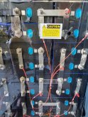
I'm still trying to come up with a good looking cover for my battery terminals.


I am just putting a piece of plexiglass or acrylic over my batteries, I don't need covers for each buss bar.

I used 20mm length M6-1.0 set screws with my 3/16" think copper bus bars. With 2 stacked bus bars, I used a 30mm. 25mm probably would have been fine. 20mm was to short to connect any sort of lug on top of the bus bar.
The picture shows the insulated 10mm wrench that I picked up for this job. Electrical tape around any wrench would accomplish the same thing. I don't recommend using a non-insulated wrench as it is very easy to have one slip and arc across + and -.
View attachment 23056
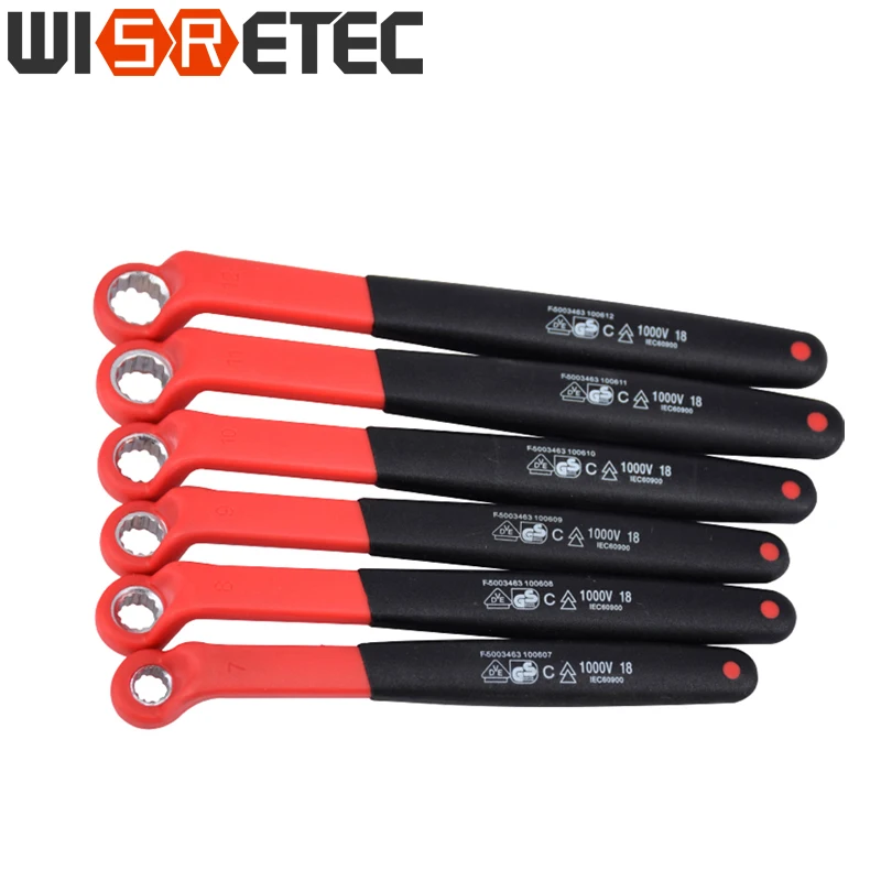


Thanks for posting the Amazon links. I ordered the same grub screws and nuts as you did. I also ordered some blue Loctite for the grub screws. They are scheduled to be delivered today. I am going to use whatever hardware comes with the cells to balance them to make sure all is well before using the grub screws.I ordered the same insulated 10mm wrench from Alibaba, washers, grub screws, DIN 6923 hex flange nuts and used my Bondus hex T handle to hold the grub screws 1/4 turn off the bottom.
I think I read somewhere about being careful not to put too much stress on the stud when mounting the terminal fuse blocks. Since mine will use a big cable I plan to attach the cable to something so it will never put stress on that terminal. I think it might be good to put a non conductive spacer under the unsupported part of the fuse block too. I bet some people make up some kind of mount for extra support so the cell terminal screw doesn't have to hold everything.Thanks for posting the Amazon links. I ordered the same grub screws and nuts as you did. I also ordered some blue Loctite for the grub screws. They are scheduled to be delivered today. I am going to use whatever hardware comes with the cells to balance them to make sure all is well before using the grub screws.
I noticed you have your MRBF fuse directly mounted to the cell. Do you intend to leave it there? I am planning on doing the same if you don't see a problem with it. I know there has been discussion about having the fuse directly mounted to the cell but in my case I don't think it will be a problem since my cells will remain stationary.
My 8 cells are scheduled to be delivered Friday. So I need to get moving on my build although I will be taking it slow. Thanks.
kaptop tape may be ugly but it works.I'm going to use kapton tape, but there are vendors on Alibaba that can sell you busbar end covers, or bubar whole covers
View attachment 23613View attachment 23614
Thanks, those are good ideas. Since I am leaning towards a 24 volt system as opposed to a 12 volt system my cables will not be too large but I will support them.....good idea. I might be able to get by with 4 AWG but I haven't even decided on an inverter yet. Using the online calculators I could get a 2000 watt 24 volt inverter and 4 AWG would be ok up to 4 feet. I don't really need a 2000 watt inverter. Anyways got to get the pack built first. Then I will decide on an inverter.I think I read somewhere about being careful not to put too much stress on the stud when mounting the terminal fuse blocks. Since mine will use a big cable I plan to attach the cable to something so it will never put stress on that terminal. I think it might be good to put a non conductive spacer under the unsupported part of the fuse block too. I bet some people make up some kind of mount for extra support so the cell terminal screw doesn't have to hold everything.