diy solar

diy solar

MPP LV6548 AC Wiring Question

I just thought I'd post here to help make clarification on the actual outputs for the MPP LV6548. I had pinged MPP and asked them about the outputs (also if it is a HF or LF inverter and how they handle imbalanced loads, amongst other things) and they replied to me with the following:


"These are high-frequency inverter, and still with transformer built in.
As long as your AC load size will not exceed the size of inverter, it will work fine.
Inverter is designed in 6500w continuous power, surge power 13kW (withhold 5 second). And for 2 inverter stacked split-phase topology, it will be a 13kW inverter system / surge power 26kW

For working under a 120v, the support output AC current is 118.18A , or under 240v AC output , it is 54.16A .
We have many different model of inverter designed in similar way, unbalance power is confirmed not an issue."


So the point I'm putting here, is that a pair of these inverters could easily exceed what a 100a AC breaker panel could handle, I would honestly rather go with a 200a AC panel to support future stacking if I added 2 more inverters later (2x per leg), because 4 inverters would double the above amp values.
I have two LV6548's running everything fine. I have two Trane 3 ton HVAC in a 3000sq ft house. I used the Emporia monitoring solution on my 200amp service box for about 7 months, to see what the max pull was. Using soft start on the HVAC, they eac pull about 2500W on start, and 2kw while running, so both around 5KW. The LV6548's provide 13KW. When the HVAC is off, my steady state for everything in the house is about 800 watts (lights, TV's, settop boxes, heat, chargers, fridge, etc...) it hits up to 2K in short spikes when the microwave is on, etc. If you check out DMI inc's and DanF's youtube channels, you can see they are able to run everything fine. Dan uses two LV6548's, and DMI has 4. Even with 4 them for 26KW continuous, its less expensive than one Sol-Ark, and Sol-ark seems to have issues when one leg is above 4KW ( that may have changed, but I have not seen any new tests after David Poz did his)
If you have not used the Emporia Energy app to monitor your house, I highly recommend it. Great little useful solution to find out what your consumption is, and who the consumers are.
Also check out DMI inc, as he is doing some very cool stuff with MPP solar and DIY batteries.
 
I can put an 11kW fully balanced 240v load on two LV6548s and it will only run for 30 minutes before it overheats. I doubt this can run a 12 kW load for more than 10 minutes.

I have asked MPP-Solar to explain it, they have no answer.

I would not be comfortable running more than 9 kW continuous with these.

The key point is that you can put 4 or 6 together for far less than the cost of a "Hardened" or "Top-Tier/Name Brand" set of units.
 
Yes, the grounds pass through the LV6548. EGC in, EGC out, and Chassis ground on those units are all connected at all times. Reading the posts that follow, I must say I am not an electrician, and I am not sure the loop is a huge deal if you leave it, but all I have read says you want no loops either neutral or earthing.
Hi All ... I'm really struggling with this ... I also have two LV6548s, and I've sure learned a whole lot about grounding electrical systems in the last two days. Frankly, these boxes just don't make any sense. Put simply, forget switches, etc, I SHOULD be able to simply run a green chassis wire from every device I have, including my inverters, to my main panel, bonded to neutral only there. Then everything I have will be nicely, and simply grounded without any ground loops, anywhere. BUT, for one, for the life of me, I cannot find a chassis ground lug on my inverters. There's only the two AC in and AC out grounds. So, huh? (And watching Will's video on this exact subject, and digging deep into the comments, he said he just followed the directions to ground the PV side to the AC side, but, again, for the life of me, I see no such directions.) And, two, when the inverters switch to Battery Mode, they bond the Neutral to Ground. Why? Are they EXPECTING me to go drive an electrode into the ground to create a separate ground for the PV side of the system only? And then I do have to worry about a possible ground loop? Also, I found this: the Phocos Any-Grid PSW-H-6.5kW-120/48V is the exact same box as the MPP LV6548, except that it has grid feedback (for $500 more) AND, thank goodness, a MUCH better manual. From the Phocos manual:

WARNING: It is highly recommended and legally required in many countries to install a Type B residual current device (RCD) between the AC output of the unit(s) and the AC loads to protect humans from hazardous electric shock due to faulty AC wiring, faulty loads or a potential inverter fault. Only in Off-Grid mode, the neutral (N) and ground (PE) of the AC output are automatically bridged inside the Any-Grid to ensure the RCD’s functioning if the AC installation is wired correctly as a TN-S or TN-C-S earthing system. In a TN-C-S installation the bridge between neutral (N) and ground (PE) must be between the public grid and AC input of the Any-Grid to ensure that there is never more than one bridge between N and PE.

So, ok, go get some Type B RCDs to prevent any DC current from getting into my house, and electrocuting one of my kids (sure wish the MPP manual mentioned this). This still does not explain the last sentence ... in a TNCS system, you're bonding at the main panel, and in this system, you're ALSO bonding within the inverter. Again, huh?!

Can someone explain this? Thanks in advance for any HELP!!! :)
Try watching this:
 
Try watching this:
So... your referenced video didn't go into any of the grounding ... but I am watching another video that I found linked underneath it, this one:
. I'm about half way through it ... thanks for pointing me in the right direction ...
 
So... your referenced video didn't go into any of the grounding ... but I am watching another video that I found linked underneath it, this one:
. I'm about half way through it ... thanks for pointing me in the right direction ...
No worries. @DanF is my hero. He has the prettiest install bar none.
 
Can someone explain this? Thanks in advance for any HELP!!! :)
Electricity will return back to the source.

Grid power uses the earth as a return. The inverter bonds N-G because it is the source. When on grid bypass, the LV6548 opens that bond.
 
Electricity will return back to the source.

Grid power uses the earth as a return. The inverter bonds N-G because it is the source. When on grid bypass, the LV6548 opens that bond.
Correct.
  • When in bypass the load is powered by the utility and the inverter can only be used to charge the batteries. So in case of a fault the current has a path back to the source (your main panel) via the ground wire and trips the breaker feeding it.
  • When on inverter (either solar or battery), it physically opens (via a contactor or relay) its connection to the main panel and needs a new GNB incase of a fault downstream.
lv6548.png
 
Electricity will return back to the source.

Grid power uses the earth as a return. The inverter bonds N-G because it is the source. When on grid bypass, the LV6548 opens that bond.

Ok, just to get some clarification for my scenario, so what if I am in an off-grid install, and my only 'grid' source will be a propane generator, then should I have an N-G bond at the generator (either with its own ground rod if far away, or connect to the same ground preferably if it is close to the MPP), to provide N-G bond for if/when the MPP's are in bypass and the generator is the new power source?

And what happens when the MPP are not in bypass but just using generator for charging the batteries, it seems there would be two N-G bonds at that point? I guess that would be the same like the power company having their upstream N-G bond...

Assuming the ladder wouldn't matter per se, since the MPP inverter circuit is still providing the AC for the house panel, and the generator is on its own circuit, providing power to the MPP battery charger circuit. I guess there would still be the two bonds but does it matter from a safety perspective here?

And would it be better to just form the other N-G bond at the generator breaker box a couple feet away from the MPP's AC input? It seems you would want it as close to the generator as possible, since it is the upstream source of power...
 
Last edited:
And what happens when the MPP are not in bypass but just using generator for charging the batteries, it seems there would be two N-G bonds at that point? I guess that would be the same like the power company having their upstream N-G bond...
If the MPP is charging the batteries from its AC input (gen or utility) then it’s in bypass. It can’t invert and charge from its AC input at the same time.
 
Last edited:
If the MPP is charging the batteries from its input (gen or utility) then it’s in bypass. It can’t invert and charge from its input at the same time.

So there's no mode I can charge the batteries only, while inverting. That doesn't seem right. I want to be inverting 100% of the time, and only have the option of using a generator to charge the batteries if I need more than the solar can provide.

I'll have to go read the manual better. If that is the case, I'd have to buy standalone AC charger for the generator.

EDIT:
Yeah, I'll be darned...


That's lame...

Well I guess that solves that problem, I'll just have to use standalone chargers and not connect AC to the MPP inputs.
 
Last edited:
So there's no mode I can charge the batteries only, while inverting. That doesn't seem right. I want to be inverting 100% of the time, and only have the option of using a generator to charge the batteries if I need more than the solar can provide.

I'll have to go read the manual better. If that is the case, I'd have to buy standalone AC charger for the generator.

If you want to always be on inverter, then yes you’ll need a dedicated AC charger.

This inverter uses the same circuitry for its inverter and AC charger so it can’t do both at the same time.
 
If you want to always be on inverter, then yes you’ll need a dedicated AC charger.

This inverter uses the same circuitry for its inverter and AC charger so it can’t do both at the same time.

Gotcha... Not sure what I had been thinking that this system could do everything at once... (so much for All-In-One). I think I even read the other thread before and forgot about this limitation, my brain is mush half the time...

I do have an AIMS 48v 25a charger though, I could use that if I wanted to charge while inverter is running, I could get a second one to double the amps...
 
Last edited:
Gotcha... Not sure what I had been thinking that this system could do everything at once... (so much for All-In-One). I think I even read the other thread before and forgot about this limitation, my brain is mush half the time...

I do have an AIMS 48v 25a charger though, I could use that if I wanted to charge while inverter is running, I could get a second one to double the amps...
And this is from the Phocos manual, which has more robust explanations (different section this time): 1643665821542.png
 
Correct.
  • When in bypass the load is powered by the utility and the inverter can only be used to charge the batteries. So in case of a fault the current has a path back to the source (your main panel) via the ground wire and trips the breaker feeding it.
  • When on inverter (either solar or battery), it physically opens (via a contactor or relay) its connection to the main panel and needs a new GNB incase of a fault downstream.
View attachment 82008
Is that AC Input / Output truly a straight pass-through? Could you please provide a link to the page you found this?
 
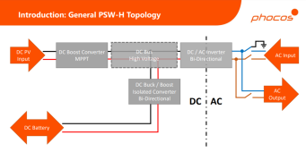
@Samsonite801 @ChrisFullPower Man, is this stuff confusing. Let me see if I've got this straight: Basically the DC to AC dotted line is Bi-Directional, but not at the same time?

Yeah, it sounds like it uses the same MOSFETs to switch for the DC battery charging from grid AC input, or the inverting from battery DC to AC output, so they can't do both at same time.
 
Is that AC Input / Output truly a straight pass-through? Could you please provide a link to the page you found this?
Yes. There’s been a few threads on here that discuss it. This is a non line interactive product.

It uses its “inverter” to convert DC from its high voltage DC bus to AC for your loads. When there isn’t enough DC power available, from either the PV or Battery, it closes it’s input contactor and powers your loads via the grid (or gen). When the input contactor is closed, it uses its “inverter” to rectify the grid/gen AC back to high voltage DC which then is passed through its DC/DC converter to charge your battery.
 
Yeah, it sounds like it uses the same MOSFETs to switch for the DC battery charging from grid AC input, or the inverting from battery DC to AC output, so they can't do both at same time.
Heh, ok, thanks. I don't think that affects my application (and I couldn't quite follow yours :) ... think I need a diagram ) ...
 
Back
Top