diy solar

diy solar

MPP LV6548 AC Wiring Question

Yes. There’s been a few threads on here that discuss it. This is a non line interactive product.

It uses its “inverter” to convert DC from its high voltage DC bus to AC for your loads. When there isn’t enough DC power available, from either the PV or Battery, it closes it’s input contactor and powers your loads via the grid (or gen). When the input contactor is closed, it uses its “inverter” to rectify the grid/gen AC back to high voltage DC which then is passed through its DC/DC converter to charge your battery.
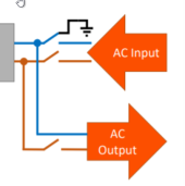
So ... if this switch were closed then the AC Input would be supplying the AC Output, the Loads directly. And it's limited to 60A in bypass (very frustrating) I assume because the internal switch circuitry size isn't large enough to handle a more typical 150A?
1643671163060.png
 
So ... if this switch were closed then the AC Input would be supplying the AC Output, the Loads directly. And it's limited to 60A in bypass (very frustrating) I assume because the internal switch circuitry size isn't large enough to handle a more typical 150A?
Well the inverter itself can only output 54 amps (6500/120) so it’s pretty typical for a non interactive inverter to only be able to bypass roughly the same amount of current it can produce.
 
I can put an 11kW fully balanced 240v load on two LV6548s and it will only run for 30 minutes before it overheats. I doubt this can run a 12 kW load for more than 10 minutes.

I have asked MPP-Solar to explain it, they have no answer.

I would not be comfortable running more than 9 kW continuous with these.

The key point is that you can put 4 or 6 together for far less than the cost of a "Hardened" or "Top-Tier/Name Brand" set of units.
I'd be monitoring battery and PV voltage if this indeed occurs. Remember, as voltage drops or sags, amperage will increase as watts demanded remains constant. Amperage makes heat.

You might find the solution there.
 
Ok, just to get some clarification for my scenario, so what if I am in an off-grid install, and my only 'grid' source will be a propane generator, then should I have an N-G bond at the generator (either with its own ground rod if far away, or connect to the same ground preferably if it is close to the MPP), to provide N-G bond for if/when the MPP's are in bypass and the generator is the new power source?

And what happens when the MPP are not in bypass but just using generator for charging the batteries, it seems there would be two N-G bonds at that point? I guess that would be the same like the power company having their upstream N-G bond...

Assuming the ladder wouldn't matter per se, since the MPP inverter circuit is still providing the AC for the house panel, and the generator is on its own circuit, providing power to the MPP battery charger circuit. I guess there would still be the two bonds but does it matter from a safety perspective here?

And would it be better to just form the other N-G bond at the generator breaker box a couple feet away from the MPP's AC input? It seems you would want it as close to the generator as possible, since it is the upstream source of power...
Well, you have a non standard situation. Different rules apply. You get into non separately derived systems and separately derived systems. https://findanyanswer.com/what-is-a-non-separately-derived-system

Does your generator manual indicate a ground rod is required? That will determine which category it fits in.

One issue you can run into is GFCI tripping (if your genny has one) as it will sense a ground fault somewhere. This thread explains why.

https://diysolarforum.com/threads/g...o-it-after-inverter-install.31397/post-380432

There are a few solutions to the N-G bond but you need to determine what type of generator you have first. One, just add a charger and use the genny to charge the batteries. Two, add a relay where the N-G bond in the main panel is disconnected. But if you have a non separately derived system: https://forums.mikeholt.com/threads/grounding-requirements-for-generator-install.10286/
 
Well the inverter itself can only output 54 amps (6500/120) so it’s pretty typical for a non interactive inverter to only be able to bypass roughly the same amount of current it can produce.
"Typical" doesn't always make sense ... this box is chalk full of pretty awesome features, except this, because in A LOT of cases, it forces a lot of rewiring. In my case a lot of rewiring for High Amp, rarely used devices. Do you happen to be aware of an auto-bypass switch I could program, or would simply switch at, say, 50A and can handle up to 150A? Then in "normal" mode (avg 30A household + dryer = 45A), I could run my Service into this switch and send it over to my PV system then to my main panel / house. If I went over 50A sustained (say above plus stove + microwave - not atypical around dinner), I'd bypass the PV and send my Service straight to my main panel. This would save me a whole lot of rewiring time ...
 
"Typical" doesn't always make sense ... this box is chalk full of pretty awesome features, except this, because in A LOT of cases, it forces a lot of rewiring. In my case a lot of rewiring for High Amp, rarely used devices. Do you happen to be aware of an auto-bypass switch I could program, or would simply switch at, say, 50A and can handle up to 150A? Then in "normal" mode (avg 30A household + dryer = 45A), I could run my Service into this switch and send it over to my PV system then to my main panel / house. If I went over 50A sustained (say above plus stove + microwave - not atypical around dinner), I'd bypass the PV and send my Service straight to my main panel. This would save me a whole lot of rewiring time ...
Ehh I don’t wanna argue but I think it’s pretty unreasonable to expect that feature on this inverter. Switching 300% of its rated output is a large ask.

If you have large loads (range, EV charger, dryer, ect) that would overload the inverter, simply leave them on your main panel and have the output of the inverter feed a “critical loads” panel that has the rest of your circuits.
 
There are a few solutions to the N-G bond but you need to determine what type of generator you have first. One, just add a charger and use the genny to charge the batteries. Two, add a relay where the N-G bond in the main panel is disconnected. But if you have a non separately derived system: https://forums.mikeholt.com/threads/grounding-requirements-for-generator-install.10286/

The generator I will use for this is an Onan 6.3kW 1800 rpm intended for an RV, where the guy I bought it from mounted it on a cart with wheels (neoprene lined wheels), and put on his own breakers and receptacles (no GFCI there)... I'll have to check it to see if it has an N-G bond already. It currently is wired with a 30a RV 120v receptacle and a 120v household 2-receptacle on it, but I believe it could be wired for 4-prong 240v receptacle no problem.

I was thinking to just ground the generator for safety once I get it in the permanent location. I will probably wire to the MPP AC input with a disconnect (for emergency charging), and now with this information about charging (being more in my forefront thought), I will make another circuit to go to some standalone battery chargers, and put a disconnect on that too, and just run the standalone chargers most the time, and be able to switch to the MPP AC input if it ever became necessary to charge that way in a bind.

I guess if the MPP never bonds neutral (in bypass) while I'd be using the onboard charger, then it doesn't hurt to just treat the generator like a power station and bond N-G there.


Ref:
1643684216082.png
 
Last edited:
Ehh I don’t wanna argue but I think it’s pretty unreasonable to expect that feature on this inverter. Switching 300% of its rated output is a large ask.

If you have large loads (range, EV charger, dryer, ect) that would overload the inverter, simply leave them on your main panel and have the output of the inverter feed a “critical loads” panel that has the rest of your circuits.
Heh, yeah, that's the problem ... I only have a few large loads I'm worried about, and to leave them on the main panel means creating a sub-panel with the bulk of my loads ... essentially rewiring almost everything. Sigh. I have no idea what it would cost to create a switch that big within one of these boxes ... this is my first foray into all of this, and it shocked me that these boxes can't simply shunt power around them ... greatly appreciate all the help ...
 
Awright everyone ... I can't tell you how helpful this forum is ... I've never experienced anything like it online before. Greatly appreciated. Anyone care to poke holes in this schematic (wire sizes, battery bank, other details TBD)? I have to get it past my small city's inspector, as there's no way they're going to miss me putting solar panels up on my roof ... thanks much in advance for any help ...

1643683950131.png
 
Awright everyone ... I can't tell you how helpful this forum is ... I've never experienced anything like it online before. Greatly appreciated. Anyone care to poke holes in this schematic (wire sizes, battery bank, other details TBD)? I have to get it past my small city's inspector, as there's no way they're going to miss me putting solar panels up on my roof ... thanks much in advance for any help ...

View attachment 82069
I am probably not reading this right, but what stands out to me is your panel ground looks like its tied to DC ground, and to ac ground.
In the MPP manual, it states that PV ground to the inverter is a nono. (I use a seperate ground rod for PV only, and in case of lightning, with SPD and lightning devices tied in)
My AC grounds are seperate, with N-G bonding only done in the main panel.
I would have an electrician who knows solar in your area help you with the diagram for the local inspection.
Because this inverter (AC output) is not isolated from the PV input, only solar panels are acceptable for use which do not require positive or negative grounding as grounding the positive or negative PV cables is not allowed. To avoid any malfunction, do not connect any PV modules with possible current leakage to the inverter. For example, positive- or negative-grounded PV modules will cause current leakage to the inverter. Grounding of the PV module frame is permitted and frequently required by local law.
The battery is galvanically isolated from the inverter and PV input, therefore the battery positive or negative terminal may be grounded if required.
 
I am probably not reading this right, but what stands out to me is your panel ground looks like its tied to DC ground, and to ac ground.
In the MPP manual, it states that PV ground to the inverter is a nono. (I use a seperate ground rod for PV only, and in case of lightning, with SPD and lightning devices tied in)
My AC grounds are seperate, with N-G bonding only done in the main panel.
I would have an electrician who knows solar in your area help you with the diagram for the local inspection.
Here's the exact language from the Phocos manual (a much more robust manual than MPP's for the exact same box -- and I just read @ChrisFullPower 's post, he cut/paste the same thing):
1643743960053.png
What I'm showing via the circles (and I'll make this more clear) is that the frames only are grounded, not the PV circuit. From what I understand (and boy is this a complex topic), this is to prevent excess build up of static electricity, ground the frame as a human's feet are grounded, just in case, and provide an easy path to ground in case of a lightning strike. The circuit itself is "floating" and doesn't need a ground, as does the Grid, because according to, I think, Will, our sponsor/hero :), the Grid is so huge that the Earth CAN act as a path back to source, so essentially we have to turn anything we might all touch that's powered from the Grid into the equivalent of the earth.

As for where to ground it ... I think, it shouldn't matter, I COULD drive in a separate electrode, as you have, except that I only want a single ground, in case of a nearby lightning strike, which might create a circuit for the strike, frying my house. So, I'm planning on simply running the DC side of the system ground to the AC ground supplied by my electrical service, because I'm pretty sure it shouldn't matter, and eliminates complexity. Having said that, I'm open to anything here ... which is why I'm posting this ...
 
@Samsonite801

I am also using the Onan 6.3 kw RV gen set for my backup power plant. These are factory wired for 120 volts 2 seperate circuits to run dual air conditioners on Class A motorhomes. They do not have a neutral ground bond from Onan. Sometimes that is changed by the motorhome builder. They have two seperate windings that can be connected as two separate 30 amp services but can also be wired as 240 volts or 120/240 volts as desired.

I do have the factory service manuals as well and through an acquaintance on another forum do have access to a treasure trove of Onan manuals that can be downloaded for free from an Onan hobbyist group.

I think that my big Onan is a model NH3, but not exactly sure right now if that is exact. I also possess 3 Onan Emerald 4 units 4.0 kw 120 volt units that have a single winding for 120 volts only.

I store all my documents in Adobe in .PDF format and am willing to share all that I have and will point you to that forum user who also has a Onan Parts business, though mostly engine parts, both new and used. He is a very avid off gridder and very willing to share. His prices on parts are hard to beat...

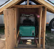
Yeah, the reason I bought this Onan 6.3 on the cart with wheels, is because my motorhome (seen behind in the above picture), also has an Onan 6.3 onboard, and I figured it's better to have 2 gensets with same parts so if one breaks, I can use the other for parts.

I have already had a chance to take advantage of this. I am off-grid like 50 miles from the nearest town, and my Onan in the doghouse shed stopped running. I troubleshot it to a bad coil, so I took the one off the motorhome and had it back up and running in minutes. Then later on at my convenience, I ordered a new coil back in town and brought it back out to fix the one back up in the motorhome, so they both run again.

I also got that second Onan because the one in the motorhome runs on liquid propane feed, and it's not easy to fill the stationary tank in the motorhome (until I come up with a remote fast fill solution)... The Onan in the doghouse runs on vapor propane directly, so no evaporator on the exhaust, it just takes the standard RV 7.5 gal vapor-feed bottles, so is easy to swap out when they run out.

I do have a vapor tee-kit plumbed in to the motorhome so I can run the motorhome furnace, fridge and stuff off the 7.5 bottles, but not for liquid yet, so I use the motorhome Onan sparingly for now. I did buy a large mobile truck propane tank, I want to see if I can put a pump on it and make it a filling station for my motorhome main tank at some point.

I would like to have access to your manuals if you don't mind. I have a couple PDFs I found on my Safari manuals disk and it was how I was able to study the ignition circuit and figure out how to troubleshoot my coil problem a little easier, but I would like to see your manuals and compare.

I had been wondering if these Onans could be wired for 240v... The Onan in the doghouse on the cart, was prewired for 2x 120v, it has one 30a RV plug, and a 20a dual 120v traditional receptacle mounted on it.

BTW, thanks a lot for taking the time to respond with helpful info :)
 
Ok so my friend has a business named Onan Parts , (onanparts.com) he is in NW Washington state. He advised me of a group of Onan users who have a website that does have a real treasure trove of hard to find Onan manuals, many hundreds of manuals and also a guide as to what manuals are for which Onan.

You can find him at (where else) onanparts.com. These manuals are gold....Onan charges big bucks for the manuals. There are 4 separate manuals for each motorhome generator set divided into unit, service, engine, and generator.
He can be found on Midnight Solar forum as user Onan Parts, he is also on this forum under another user name, Im not at liberty to reveal that name.

I have downloaded all the manuals for my Emerald 4.0 units as well as the manuals for the NH-3 6.3 kw. unit and the guide to “which manual for which Onan”

Willing to help if needed...

Cool thanks, I will check it out. I grew up right around there in the PNW Washington by Bellingham area, I wonder if I know him hehe, probably not.
 
My Onan is also on wheels on a cart much like yours, When after a long dry summer it will pump water from my deep well when the current draw is large enough to make my magnasine stumble, I would rather not drive my off grid system to its limits. I am planning a wood gasifier to power the Onan on renewable energy.

I do also have a motorhome with a Onan generator I do refill the motorhome tank using portable tanks, its not difficult , just a POL to POL hose with the portable tank hung upside down in the sun so it is hotter than the tank under the motorhome, takes under 10 minutes to transfer the 5 gallon tank into the motorhome tank without needing to open the vapor release valve.
 
One of my favorite tromping grounds is Port Townsend, Washington. I had to leave when the billboards in Seattle stated “Will the last person leaving Seattle please turn out the lights”
 
My Onan is also on wheels on a cart much like yours, When after a long dry summer it will pump water from my deep well when the current draw is large enough to make my magnasine stumble, I would rather not drive my off grid system to its limits. I am planning a wood gasifier to power the Onan on renewable energy.

I do also have a motorhome with a Onan generator I do refill the motorhome tank using portable tanks, its not difficult , just a POL to POL hose with the portable tank hung upside down in the sun so it is hotter than the tank under the motorhome, takes under 10 minutes to transfer the 5 gallon tank into the motorhome tank without needing to open the vapor release valve.

I just saw a bunch of videos on building wood gasifiers like maybe a week ago, never heard of them prior. So I downloaded the PDF how-to from FEMA website and a couple others. I'd like to try that as well, I did see the You Tube video where the guy ran a little generator off it and powered a power tool for demonstration...

On the propane filling thing, I did ponder to just do the simple gravity-fill method, and since my big truck tank I bought will be inside my box truck bed (probably mounted to a pallet), it sits way higher, higher than the RV tank, and I was thinking to also make hoses to bridge the vapor lines, as well as the liquid lines, so then you wouldn't have to open the vent valve and blow it outside, just open both liquid and vapor valves on both tanks, and let it gravity feed the liquid, and the vapor would vent and displace to the filling tank until you get to 80% max and stop it so you don't overfill. Or if it's starting to get close to 80% max, then just open the vent near the end so you can see when it starts coming out or something, but it has the needle to watch too... But if I could find a pump that is certified for propane use, that would be cool too, or even a hand pump...
 
Last edited:
I do not open the propane vent valves, propane pressure is directly related to the temperature, I do the transfer early in the day when the motorhome tank is cold and I leave the transfer tank in the sun. The difference in temperature is quite enough to fill the motorhome tank in under an hour with no venting. It is possible to overfill using this method so I do check with the vapor bleed valve when nearing full.
 
Back
Top