diy solar

diy solar

Pack / Cell compression Optimized By Using Springs.

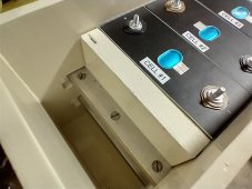
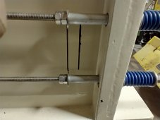
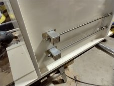
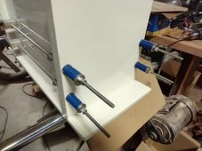
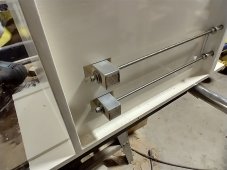
Finally seeing the end of this box build. I'm having a lot of trouble wrapping my head around this much compression on these cells. I've only tightened the 4 150 pound rated springs to half the rate and it's just seeming way too tight to me. Are you guys really doing 600+ psi on these cells? Not sure if I have the nerve to do it.IMG_20230302_163950314_HDR.jpgIMG_20230302_164013903_HDR.jpgIMG_20230302_164025319_HDR.jpgIMG_20230302_164033936_HDR.jpgIMG_20230302_164048837_HDR.jpg
 
Finally seeing the end of this box build. I'm having a lot of trouble wrapping my head around this much compression on these cells. I've only tightened the 4 150 pound rated springs to half the rate and it's just seeming way too tight to me. Are you guys really doing 600+ psi on these cells?
hello! disclaimer, i am amateur and don't have special knowledge about springs.

first off, the notch design you have with the compression is really cool in my opinion

600psi+ definitely nobody is doing this. perhaps you mean 600 pounds of force across the entire side?

to figure the pounds of force, multiply the surface area of the side receiving compression by the pounds per square inch (psi)
area * pressure -> force or (square inch) * (psi) -> (pounds)

of course the psi figure should be sourced from the specific cell being used, the manufacturer datasheet. same for surface area.

it looks like the springs are fully compressed? unsure if this poses any issue. i usually try to have a little space left, not really sure why, can't articulate it in a clear engineering way.

hope this helps in some way. nice looking build.
 
Finally seeing the end of this box build. I'm having a lot of trouble wrapping my head around this much compression on these cells. I've only tightened the 4 150 pound rated springs to half the rate and it's just seeming way too tight to me. Are you guys really doing 600+ psi on these cells? Not sure if I have the nerve to do it.View attachment 137655View attachment 137660View attachment 137661View attachment 137662View attachment 137663
I’m compressing to about 640lbs.
 
Buy two more springs and use six in your build.
That wouldn't work too well for my case. My box is kind of designed for 4 rods. I've ordered a couple of 188 pound springs a half inch longer than the ones I have. I'm still having trouble wrapping my head around putting over 600 pounds on these batteries.IMG_20230302_164025319_HDR.jpg
 
That wouldn't work too well for my case. My box is kind of designed for 4 rods. I've ordered a couple of 188 pound springs a half inch longer than the ones I have. I'm still having trouble wrapping my head around putting over 600 pounds on these batteries.View attachment 137720

This has been posted in other threads and maybe it will help here. Sounds like the cells might be over compressed.

Not using springs in compression fixture. Just using yellow pine wood 1 inch x 10 inch cut to length and four 1/4 inch course threaded rods with 1/4 inch nuts & washers on the 8s Lifepo4 battery banks.

This is Info I used and torqued a little less at 5 Inch Pounds with a torque wrench at about 3.2 to 3.3 volts charge in each cell.

The spec from EVE was 300 KG force which rounds off to 660lbs. Battery face is approx 6.85"x 7.874" = 53.94 sq inches
660lbs/53.94sqin=12.23 lbs per sq inch
Divide 660 by 4 bolts that's 165 lbs Axial (clamping) force per bolt.
Using 4 course 1/4 in threaded rods that should equate to roughly 8 INCH pounds torque per bolt. Realistically, that's a snug twist of the wrist on a regular nut driver for the average build mechanic.

Hope it helps...
 
Actually, EVE's diagram shows 6 compression rods, not 4
I've never seen any diagrams from EVE. If any exist can you provide a link. I'd love to actually see any fixtures the manufacturers suggest. Both plates on the ends of my cells are a full inch thick quality plywood and my cross bars are reinforced 1"x1" oak. I'm confident that any deflection will be insignificant.
 
This has been posted in other threads and maybe it will help here. Sounds like the cells might be over compressed.

Not using springs in compression fixture. Just using yellow pine wood 1 inch x 10 inch cut to length and four 1/4 inch course threaded rods with 1/4 inch nuts & washers on the 8s Lifepo4 battery banks.

This is Info I used and torqued a little less at 5 Inch Pounds with a torque wrench at about 3.2 to 3.3 volts charge in each cell.

The spec from EVE was 300 KG force which rounds off to 660lbs. Battery face is approx 6.85"x 7.874" = 53.94 sq inches
660lbs/53.94sqin=12.23 lbs per sq inch
Divide 660 by 4 bolts that's 165 lbs Axial (clamping) force per bolt.
Using 4 course 1/4 in threaded rods that should equate to roughly 8 INCH pounds torque per bolt. Realistically, that's a snug twist of the wrist on a regular nut driver for the average build mechanic.

Hope it helps...
That math works out the same as mine. I do prefer springs to accommodate any expansion that might take place within the cells. I'll be using 4 188 pound rated springs compressed to 165 pounds each.
 
That math works out the same as mine. I do prefer springs to accommodate any expansion that might take place within the cells. I'll be using 4 188 pound rated springs compressed to 165 pounds each.
Use the compression rating and the spring deflection, the 'torque on the bolts' method is not as accurate. The threads in the bolts and nuts are not completely even and smooth.
 
I've never seen any diagrams from EVE. If any exist can you provide a link. I'd love to actually see any fixtures the manufacturers suggest. Both plates on the ends of my cells are a full inch thick quality plywood and my cross bars are reinforced 1"x1" oak. I'm confident that any deflection will be insignificant.

Ran across this EVE LF280K spec sheet with diagrams dated April 2022. The Testing Cell Clamp diagrams are shown. It is interesting that it shows 10mm metal plates 6 M6 bolts on a single cell.
 

Attachments

  • RD-EVE LF280K-S04-LF.pdf
    2.8 MB · Views: 34
Last edited:
That spec indicates... "It can be seen from the above table, that the
compression force of the battery cannot exceed 50 kN,
otherwise the battery may be damaged."
A 50kN force is equal to just 7.25PSI - The target PSI I've read on these batteries is 12PSI-15PSI?
 
Double check the math.
I just used a web site to convert 50kN to 11240 lbs.
173.7 x 204.4 mm = 55 in^2
11240/55 = 204 psi.

Did I get that correct?
 
That spec indicates... "It can be seen from the above table, that the
compression force of the battery cannot exceed 50 kN,
otherwise the battery may be damaged."
A 50kN force is equal to just 7.25PSI - The target PSI I've read on these batteries is 12PSI-15PSI?
The compression spec is 300 kgf +-20 not 300 kn.
 
It's a quote from the eve280k spec posted above.
I guess the assumption of 50kn/m2 but no other denominator makes sense.
 
I just downloaded the newer datasheet for EVE LF280K cells from June 2023 from here (thanks). On these cells, Eve applied a clamping force of 300 kgf for all tests. Elsewhere in the document (section 4.4.2), they describe a minimum of 3000 Newtons (roughly the same value, with gravity at sea level) as the minimum, 7000 Newtons as the maximum value of the 'recommended' range. That minimum is 661 pounds. The dimensions of the large sides are 204.6 "height" (excluding the terminals) and173.3 "length" sideways, an area of 35457.18 square mm. That's 54.96 square inches. The 661 pound force is 12.0 PSI, and that's the minimum recommended value.

They used clamping plates of 10mm thickness (almost .40 inches), with 6 bolts applying clamping force (not just 4). They used bolt size M8 (not M6), although M6 or 1/4 inch steel rod can probably also handle a tensile force 110 - 180 lbs per rod without breaking. In my previous 4S battery pack builds with smaller cells, I have used 1/4" steel plates (insulated) to apply lower clamping forces, and I saw those plates begin to warp when I the compression springs all the way in.

I have already purchased 1/4" compression plates for my new LF280K battery pack, but I will also be adding add 3 segments of horizontal L-Bar across the plates (on the plates, underneath the springs) to reduce the tendency of my thinner plates to warp. (Pictures coming after the parts arrive.)
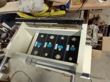
NEW NOTE 2024-07-07: I have built an effective containment for these cells at relatively low cost, applying 720 lbs minimum pressure. That thread is at
https://diysolarforum.com/threads/r...containment-for-eve-cells-lf280k-lf304.78285/
 
Last edited:
I just downloaded the newer datasheet for EVE LF280K cells from June 2023 from here (thanks). On these cells, Eve applied a clamping force of 300 kgf for all tests. Elsewhere in the document (section 4.4.2), they describe a minimum of 3000 Newtons (roughly the same value, with gravity at sea level) as the minimum, 7000 Newtons as the maximum value of the 'recommended' range. That minimum is 661 pounds. The dimensions of the large sides are 204.6 "height" (excluding the terminals) and173.3 "length" sideways, an area of 35457.18 square mm. That's 54.96 square inches. The 661 pound force is 12.0 PSI, and that's the minimum recommended value.

They used clamping plates of 10mm thickness (almost .40 inches), with 6 bolts applying clamping force (not just 4). They used bolt size M8 (not M6), although M6 or 1/4 inch steel rod can probably also handle a tensile force 110 - 180 lbs per rod without breaking. In my previous 4S battery pack builds with smaller cells, I have used 1/4" steel plates (insulated) to apply lower clamping forces, and I saw those plates begin to warp when I the compression springs all the way in.

I have already purchased 1/4" compression plates for my new LF280K battery pack, but I will also be adding add 3 segments of horizontal L-Bar across the plates (on the plates, underneath the springs) to reduce the tendency of my thinner plates to warp. (Pictures coming after the parts arrive.)
I built a 300kgf clamping fixture for my older-generation 280Ah EVE cells but that was nominal with a minimum something below that (200Kgf?).

For the LF280K cells EVE is now saying that 300Kgf is the minimum force to be applied when the battery is fully depleted and as long as the maximum force at full charge is no more than 700Kgf.

I get nowhere near 2X the force at full charge so if I calibrate my clamping fixture for 300Kgf at lowest SOC% (I am bottom-balanced so can get all the way down to 5% SOC), the force near 100% SOC (realistically 90% SOC) will be well under 600Kgf, probably even under 500Kgf).

Did Eve indicate anything about the impact of clamping at under 300Kgf at say 150Kgf versus clamping to 300Kgf at ~0% SOC?

My takeaway from this is that while the old guidelines focused on 300Kgf near ~50% SOC and then provided some general guidelines about minimum and maximums, they are now specifying a full 300Kgf at the minimum SOC and further specifying that springs should bd chosen to limit the maximum force to no more than 233% at full SOC…

It’s a much clearer spec.

Next time I break down my battery for service, I’ll plan to calibrate for 300Kgf at lowest SOC%…
Let me clarify a a couple of bits: They specified the 300 kgf clamp to be applied at SOC between 15% and 40% (not at "fully depleted" SOC, and not as low as you plan to push your cells). 15% SOC is already near the minimum limit which many of us try to enforce via BMS tuning, even though EVE ran cells to the bitter end (2.50 volts, zero percent) in their capacity tests.

I agree with you that the maximum force should not reach anywhere near 700 kgf in a properly built spring loaded clamp: The springs should not bottom out "solid" or have such a high rate (lbs per inch) that the resulting increase in force becomes anywhere near 700 kgf if the springs have been chosen properly. But the total decrease in spring length, cuased by cell expansion, varies with the number of cells in a row - the change in total thickness of my 4S "12v" battery packs are only 1/2 and 1/4 as much as total change which would occur for 8 or 16 cells arranged in a single row (respectively). I can imagine the force on cells in a 16s "single row" arrangement to be doubled, under high SOC and temperature - and I'd be incllined to construct such a "48v" battery pack as dual rows of 8 cells, to reduce the amount of movement near the ends of the rows.
- - -
Eve did not say anything about the expected results of insufficient clamping forces, I assume that they would be more serious (over time) when large variances in cell thickness are "allowed" by smaller clamping forces, and with frequent changes in SOC and temperature. In my own application (living space with in a travel trailer, SOC held between 14% and 98.5%, top balancing only from 96% upwards) I SWAG that the 8000+ cycle life might be degraded to only 2000-3000 cycles - a degradation even worse than operating at high temeratures all the time.
 
Last edited:
Let me clarify a a couple of bits: They specified the 300 kgf clamp to be applied at SOC between two 15% and 40% (not at "fully depleted" SOC,
An even more precise spec - thanks.

Whatever the recommended minimum clamping force that was recommended for lowest SOC, I applied that at about ~20% SOC.

So sounds like next time I am there, I should just apply the full 300Kgf…

and not as low as you plan to push your cells). 15% SOC is already near the minimum limit which many of us try to enforce via BMS tuning, even though EVE ran cells to the bitter end (2.50 volts, zero percent) in their capacity tests.
I never drive my cells under 20% SOC under normal use. But since they are bottom balanced, I can push down to 15%, 10% or even 5%. I’ll generally do this once or twice a year just to let my active balancer improve the quality of my bottom balance…

300Kgf calibrated at 15-20% SOC seems like the way to go (for us bottom-balancers…).
I agree with you that the maximum force should not reach anywhere near 700 kgf in a properly built spring loaded clamp: The springs should not bottom out "solid" or have such a high rate (lbs per inch) that the resulting increase in force becomes anywhere near 700 kgf if the springs have been chosen properly. But the total decrease in spring length, cuased by cell expansion, varies with the number of cells in a row - the change in total thickness of my 4S "12v" battery packs are only 1/2 and 1/4 as much as total change which would occur for 8 or 16 cells arranged in a single row (respectively). I can imagine the force on cells in a 16s "single row" arrangement to be doubled, under high SOC and temperature - and I'd be incllined to construct such a "48v" battery pack as dual rows of 8 cells, to reduce the amount of movement near the ends of the rows.
I’ve got a single row of 16 280Ah cells and once the pack has settled in (over 5-10 cycles),the total travel I get is minuscule - less than 1/8” total between my depleted SOC and my highest SOC.

Since my 300kGf springs can accomodate more than 1/2” of travel within +/-10% of 300Kgf, it’s a non-issue…
- - -
Eve did not say anything about the expected results of insufficient clamping forces, I assume that they would be more serious (over time) when large variances in cell thickness are "allowed" by smaller clamping forces, and with frequent changes in SOC and temperature. In my own application (living space with in a travel trailer, SOC held between 14% and 98.5%, top balancing only from 96% upwards) I SWAG that the 8000+ cycle life might be degraded to only 2000-3000 cycles - a degradation even worse than operating at high temeratures all the time.
Is the new spec for the LF280K with correct clamping force now 8000 cycles???

That’s 22 years to 80% capacity…

I suspect calandra aging will reduce cell capacity under 80% before then,
 
Back
Top