diy solar

diy solar

Pack / Cell compression Optimized By Using Springs.

I am struggling with 2 fixture design issues I would appreciate anyone’s perspective on (and especially those that actually have a working fixture already):

1/ single-rod vs. dual rod: I was originally thinking I would go with a single-rod design, meaning one pair of threaded rods compressing a horizontal 1-1-4” square tube on either end (crossing the middle of plastic of wooden ‘ends’) but I’m now worried that design may allow the ends to tip/angle so that expansion at the bottom of the cells may exceed expansion at the top of the cells. I’m not sure a bit of ‘accordion’ expansion is a problem (and have the flexible busbars to accommodate it) but the dual-rod design (meaning 2 square tubing braces per end) assures more uniform pressure and the only negative is the additional cost.

2/ single-spring vs. dual-spring: with a spring on only one end, the cell farthest from the spring is only going to move ~1/4mm while the cell closest to the spring will move ~3-1/2mm (for my 8S pack), while with a half-length spring on either-end of each rod, the two central cells will only move ~1/4mm while the outermost cells will only move ~1-3/4mm. Less movement is probably good, more symmetrical movement is probably good, but the main thing making me think I may want to put springs on either end of each tod is that that means the rods themselves don’t move and can be used as the primary support beams for the entire structure with the cells themselves just ‘floating’ in between the two pressurized endcaps. It means twice as many springs but if they cost 1/2 as much, it’s pretty much a no-brainer. If the total investment on springs is double, I’m not sure the minor benefits would be worth it.

I think the flexing issue has been "answered" but I can tell you that my 0.6" plywood flexed in the middle with my 4-rod construction before I added the square tubes. Imagine hanging the board 4" off the end of the table and then placing 300 pounds of pressure at the end - would it flex at all? even 1mm of flex throws all the calculations off.
 
Im not going to take the time to look them up but anything that delivers that much force over that small a distance does not appeal to me. Being able to use crude measurements to make fine adjustments vs having to be very precise to achieve the same level of accuracy. Said it several times, this is all a lot of personal preference. The original question about using 8" spring was simply a though experiment to discuss the topic for those who would be interested in having a very accurate, easy to adjust compression jig and had the room to do it.
I don’t know what you see as ‘crude’ about the measurements we are making for this.

The 5/16” rod has 18 threads per inch (1.41mm/turn) and it pretty easy to control turns to within +/-1/16th turn = 1/8th turn = 0.18mm.

The spring I’m considering has a rate of 389 lbs/inch or 15.3lbs/mm.

So with a precision of 1/8th turn or 0.18mm of precision, pre-load can be controlled to within 2.76lbs or 0.05psi.

I spoke to the sales rep and confirmed that this is exactly the correct manner to set preload (he even called me the ‘perfect customer ;)).

And I also learned something very interesting from him: if you preload one of their springs to solid (just once) it will not fully spring-back (so that is definitely something you want to avoid and it makes me wonder about Lee Springs in that regard).

Any preload exceeding their Max compression risks the spring not springing back to it’s full initial Free Length, so at least with those springs, you want to be conservative and calibrate Free Load from Free Length upward...

The Max compression results in lower cycle life of the Spring returning to its full initial Free Length, but since we are talking about 100s of thousands if not a million cycles, this is a non-issue for our application.
 
Well this is embarrassing. I do have some formal ME education. Tunnel vision is a real thing! Standby for updated calcs.

:)

I tended to do that to professors (detached from real world) and Stanford PhD's.

A guy could calculate the curl, determine derivative, generate contour plots ...
but he didn't understand how heat flows, wouldn't understand that when tide is flowing into the bay there is a depth difference at the end (and depth difference tells you water is flowing), if he was a surveyor could generate a topo map but wouldn't be able to predict where runoff would flow. He is the author of a book and an instructor on the topic.

I bought his book (just so I could mock him with his own words), and it dove quickly into integral calculus of 3-dimiensional problems. But it also cited the errors he was making.

Wouldn't accept when measurement results didn't match his simulations ...

I've had to learn, too. Passed myself off as an RF and analog expert, but learned from others along the way. It was only from on-the-job feedback and reading app notes that I learned the pitfalls of using op-amps as comparators, had to re-engineer some of my circuits.
 
I don’t know what you see as ‘crude’ about the measurements we are making for this.

The 5/16” rod has 18 threads per inch (1.41mm/turn) and it pretty easy to control turns to within +/-1/16th turn = 1/8th turn = 0.18mm.

The spring I’m considering has a rate of 389 lbs/inch or 15.3lbs/mm.

So with a precision of 1/8th turn or 0.18mm of precision, pre-load can be controlled to within 2.76lbs or 0.05psi.

I spoke to the sales rep and confirmed that this is exactly the correct manner to set preload (he even called me the ‘perfect customer ;)).

And I also learned something very interesting from him: if you preload one of their springs to solid (just once) it will not fully spring-back (so that is definitely something you want to avoid and it makes me wonder about Lee Springs in that regard).

Any preload exceeding their Max compression risks the spring not springing back to it’s full initial Free Length, so at least with those springs, you want to be conservative and calibrate Free Load from Free Length upward...

The Max compression results in lower cycle life of the Spring returning to its full initial Free Length, but since we are talking about 100s of thousands if not a million cycles, this is a non-issue for our application.
Im not doing this with you or going to derail the thread again. If you cant figure out what was meant by what was said, Im at loss.
 
I think the flexing issue has been "answered" but I can tell you that my 0.6" plywood flexed in the middle with my 4-rod construction before I added the square tubes. Imagine hanging the board 4" off the end of the table and then placing 300 pounds of pressure at the end - would it flex at all? even 1mm of flex throws all the calculations off.
Pretty sure we are talking about different flex.

I understand that without a reinforcing beam such as square tubing, wood in general and plywood in particular will flex, primarily side-to-side (the center will push out more than the sides where the springs are positioned).

What I am talking about is the difference between a single central beam across the ends halfway up versus the classic 2-beam design crossing the ends at 1/3 and 2/3 or 1/4 and 3/4 (or whatever),

Especially since if I go with wooden ends I’ll use 2x8 with vertical grain, I’m not too concerned about any flex in the vertical direction (and I’m not concerned about flex in the horizontal direction with 1-1/8th square tubing, whether single-through-middle or double-high-and-low).

What I am possibly worried about with a single support beam across the middle of the ends is that the ends may be able to pivot/rotate (not flex) so that the bottom of the cells can continue to expand more than the top.

Your dual-beam fixture eventually settled into uniform 4mm of expansion along the entire height of the cell.

My unfixtured cells expanded more at the bottom than the top (possibly because of the solid busbars) and I’m concerned that if I only go with a single pair of threaded rods and a single 1-1/8th square-tubing beam across the middle of either end, that non-uniform ‘pyramid’ expansion may continue...

Cutting the hardware cost in half is appealing, but not if it is going to introduce a new problem...

Of course, since I have two 8S batteries and only need one for now, the option I’ll probably choose is to purchase all of the hardware for 2 single-beam designs, build three first of those, and if I’m unhappy with how it performs, move the existing beam and add a second.

There is also one other Forum Member who has already built a single-beam fixture, so I may just hold off a bit longer before finalizing my plan to await his first test results...
 
I had considered that as a concern but decided it was not a significant issue because:
  • They are supposed to be under the load so assessing their physical dimensions not under load is not something that can really be evaluated.
  • When stacking cells together, if the areas that have bulged are in different locations (one in the top half and the next one in the bottom half vs two cells where the swelling is both in the middle) the overall dimension is meaningless.
I am adding 3mm drawer liner to the sides of each and every cell to help mitigate. I appreciate the solution is not perfect but using springs is a far from perfect solution in the first place so as long as I am kind of in the ball park Im happy. The biggest reason I am using springs is so I dont severely over compress.

The pressure is not dependent on state of charge. It is a constant pressure regardless of SOC. It is not a pressure based on SOC. There are a bunch of theories floating around on where the target pressure should be set but they are all speculation and best guesses. The springs I chose have a large difference between free and solid dimension and a relatively low spring rate so as the cells expand and contract based on their state of charge there will be relatively little change in force on the cells so Im setting mine at 50% soc. They are 4 inch spring but I have room so I get that luxury.

I don’t know what you see as ‘crude’ about the measurements we are making for this.

The 5/16” rod has 18 threads per inch (1.41mm/turn) and it pretty easy to control turns to within +/-1/16th turn = 1/8th turn = 0.18mm.

The spring I’m considering has a rate of 389 lbs/inch or 15.3lbs/mm.

So with a precision of 1/8th turn or 0.18mm of precision, pre-load can be controlled to within 2.76lbs or 0.05psi.

I spoke to the sales rep and confirmed that this is exactly the correct manner to set preload (he even called me the ‘perfect customer ;)).

And I also learned something very interesting from him: if you preload one of their springs to solid (just once) it will not fully spring-back (so that is definitely something you want to avoid and it makes me wonder about Lee Springs in that regard).

Any preload exceeding their Max compression risks the spring not springing back to it’s full initial Free Length, so at least with those springs, you want to be conservative and calibrate Free Load from Free Length upward...

The Max compression results in lower cycle life of the Spring returning to its full initial Free Length, but since we are talking about 100s of thousands if not a million cycles, this is a non-issue for our application.
What is the catalog item number of the spring you are considering? Please.
 
Pretty sure we are talking about different flex.

I understood what you meant -- I wanted you to know that the plywood flexed, so I would be concerned about the pyramid affect in your single beam design, for sure.
 
If I came off as harsh, my apologies. I was considering that exact same spring for those exact same reason (space to burn, so why not maintain as close to 12.1psi as possible?).

The two things that have caused me to reconsider are:

1/ 36” length of my 5/16” threaded rod - I’ve got an 8S pack of 280Ah cells which adds up to just shy of 24”. Add 1-1/8” per side for square tubing, 1-1/2” per side for ends made out of 2x8, and at least 1/2” for nuts and washers on both ends, and suddenly I’m down to ~6-1/4” and no longer have room for an 8” spring unless I move up to 48” threaded rod...

2/ I was originally designing for my measured (unconstrained) expansion, which was over 8mm for eight cells. Now that others have reported that 1/2mm per-cell expansion is all you’ll have to deal with once the cells have settled down through s few cycles in the fixture, it changes the math significantly. If I can majntain anywhere between 10.1psi and 14.1psi (with headroom for an additional 2-4mm of unexpected expansion), I’ll be pretty pleased...
 
I understood what you meant -- I wanted you to know that the plywood flexed, so I would be concerned about the pyramid affect in your single beam design, for sure.
Cool, thanks. That’s probably going to nudge me towards the classic 2-beam design like you used...
 
What is the catalog item number of the spring you are considering? Please.
9-1205-21 is the Spring I was looking at for a single-beam (single pair of rods), dual spring (spring in either end of each rod) design. [ie: 4 of these springs total]

I’ll need to find other springs if I want to go with a classic dual-beam design (whether single-spring or dual-spring)...
 
I'm planning to compress my single-row 8s battery with springs, however my guess is that the expansion is not equal across a cell's width - surely it expands more in the middle than at the edges? So I'm considering adding a resilient material between each cell, in addition to the springs providing clamping force, to allow a bit of flexibility for some cell bulge. Something like a 1/4" rubber mat. Thoughts?
 
Electrical insulation sounds good, since we hear metal case has electrical contact.
People have had their cells maintain spacing where secured, bulge where not. Seems like something extrudes, like biting into a pb&j sandwich.
Given that they're pouches of rolled layers, I'd expect it to try to expand everywhere. But edges are constrained by the can.
I would try to spring-load it between flat surfaces, but use compliant busbars.
 
I'm finding that my cells remain perfectly flat if they're under compression, so I wouldn't worry too much about it - as long as the end plates are rigid enough to spread out the pressure provided by the springs, all the cells inside will be fine. The only reason I used 1/16" neoprene is because I'm in a mobile application and I really want to prevent movement and/or abrasion.
 
Good to hear that the cells stay flat. I'm also building for a mobile application, so those are good points about preventing abrasion and electrical contact. I'll look into adding something, but I won't worry about it having much resilience.

Now on to spring force calculations!
 
I thought Id stick this in here for some feedback. My original intention was to go with no springs but I always knew there was a decent chance Id end up using them.

The logic I used for the design is to try to eliminate strain on the terminals while using bus bars. I believe the usual arrangement of having the cells connected to the one above/below it (in the picture below) instead of left/right it will result in lateral load on the terminal. The spring is there to provide the compression but also allow a degree of movement as the cell expands and contracts over its charge cycle. This must result in load on the terminal if a solid bus bar is used.

Connecting the cells left/right will result in the string moving relative to the string above/below it but not in relation to the cell it is connected to. I concede that there is an amount of unavoidable movement and vibration (mobile application). Using a belleville washer on the terminal will mitigate any rotation at the terminal caused by uneven expansion and contraction of connected cells and twisting of the pack. Crossing fingers and hoping vibration due to mobile application will be tolerated. The vehicle its going in has 14" of plush suspension travel (6 up and 8 down) so hoping it is ok.

The build as it sits today:
  • The series strings will run left/right and will be paralleled at the left/right ends.
  • There is an air gap 360 degrees around the narrow side.


View attachment 36502


View attachment 36503

Future steps (no particular order):
  • Springs
  • Insulation
  • Bottom heater, Induced draft fan for top and thermostat
  • SBMS thermocouple install
  • Epoxied, vented studs
  • 1/16"X 1.5" Aluminum bus bars (max current from each string will be in the area of 125A)
  • 3mm foam liner applied to plywood/cell broad side contact to help provide more even pressure to cell sides
  • A small plywood block on top of the cells between terminals to fully capture the cell in jig.
Any constructive criticisms welcome!

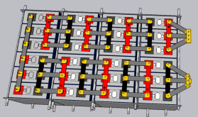
I like the look of this. Its closest to my thoughts at this stage.. My complication is I'm doing a 24 cell , 24V pack as 4 rows of 6 cells. Since each 'triplet' needs busbars, the complication of allowing movement means more complex connections of the 3. As designed below with 20mm x 1mm busbars tripled between all sets of 3 (plus one doubled across the back on all 6 terminals). I'm now leaning to a compressible layer between all batteries of a neoprene material, compressed to about 2mm between cells, under a fixed bolt compression. I have no confidence the resilience of the neoprene will remain constant under 2000+ cycles , and as to how to calculate approx pressure for another 1mm compression would be complex.

I'm in awe of the great work all you guys are doing in this thread, attacking a thorny issue that seems to be ignored by most commercial pack battery makers.
 

Attachments

  • packplan.png
    packplan.png
    281.4 KB · Views: 37
Here you go guys! I found out the hard way that 20 pictures is the max for one post.... It's a start and hopefully some ideas to build on using springs!
Fantastic, now that I see how you DIY your flexible busbars, I might revisit my decision to not go springs, for fear of movement of cells on fixed simple rigid 3 post busbar. I could make a 3 cell busbar in one with 2 flexi bits between allowing for movement. How many amps is that braided stuff rated for ? I need 200 Amps to be safe on my design ?
 
Back
Top